Supercharge Your Innovation With Domain-Expert AI Agents!

Combined heat and power generation device and method based on carbon dioxide conversion and utilization

A carbon dioxide, cogeneration technology, applied in steam engine installations, oxygen production, steam application, etc., can solve the problems of difficult carbon dioxide gas disposal, high carbon capture cost, greenhouse effect, etc., to improve comprehensive energy utilization efficiency and product quality. Excellent, high economic value effect

Pending Publication Date: 2022-07-01
刘小江 +1
View PDF0 Cites 0 Cited by
  • Summary
  • Abstract
  • Description
  • Claims
  • Application Information

AI Technical Summary

Problems solved by technology

Much carbon is captured by storing it as gaseous carbon dioxide, which is significantly more expensive to store and transport, and can easily leak back into the air, contributing to the greenhouse effect
[0003] In order to efficiently solve the problem of carbon neutralization of carbon peaks, it is necessary to jointly produce carbon sheets or graphene in thermal power plants at the source of carbon dioxide generation, so as not to dispose of the carbon dioxide gas produced by them is difficult or costly. Based on this, research and development are urgently needed A cogeneration device and method based on the conversion and utilization of carbon dioxide is developed to solve the technical problems of high carbon capture costs and waste of resources caused by cogeneration in the prior art

Method used


Image

  • Combined heat and power generation device and method based on carbon dioxide conversion and utilization
  • Combined heat and power generation device and method based on carbon dioxide conversion and utilization
  • Combined heat and power generation device and method based on carbon dioxide conversion and utilization

Examples


Embodiment Construction

[0020] The present invention will be further described below with reference to the accompanying drawings and specific embodiments.

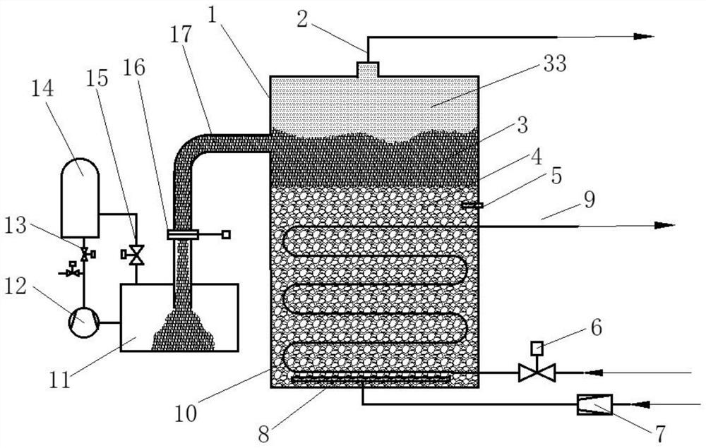
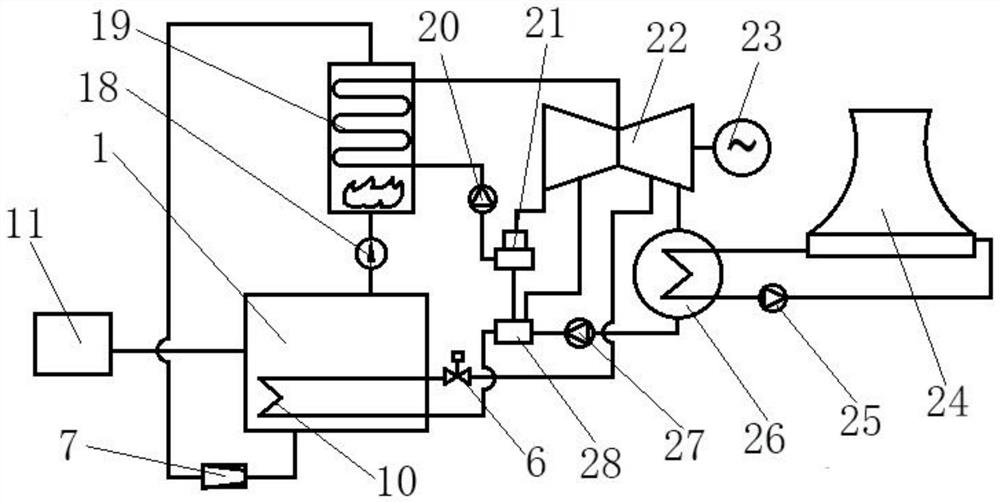
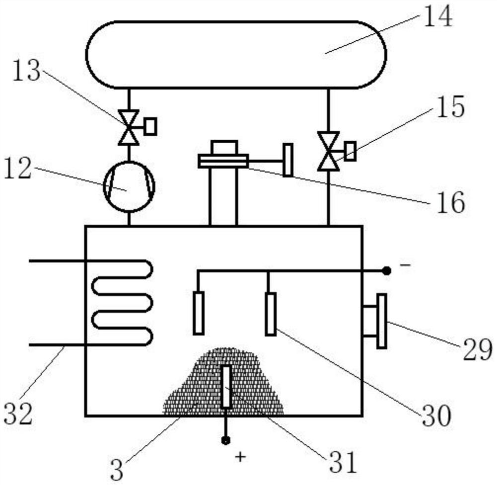
[0021] like Figure 1 to Figure 3 As shown, a cogeneration device and method based on carbon dioxide conversion and utilization, comprising a reactor 1, an oxygen delivery pipeline 2, a carbon sheet 3, a liquid alloy 4, a temperature probe 5, a steam flow control valve 6, a carbon dioxide compression device 7, Carbon dioxide distributor 8, steam pipeline 9, heater 10, carbon sheet reaction box 11, air compressor 12, pressure relief valve 13, pressure balance tank 14, pressure balance valve 15, closing valve 16, carbon sheet conveying pipeline 17, oxygen Conveyor 18, boiler 19, booster pump 20, deaerator 21, steam turbine 22, generator set 23, cooling tower 24, condensate circulating pump 25, condenser 26, condensate transfer pump 27, condensate heating device 28, The material taking port 29 , the negative electrode arc rod 30 , the positive elec...


PUM


Abstract

The invention discloses a combined heat and power generation device and method based on carbon dioxide conversion and utilization. The input end of a carbon dioxide cracking device communicates with the output end of a combined heat and power generation system through a steam pipeline; a carbon dioxide distributor is arranged at the bottom of the reaction kettle, the input end of the carbon dioxide distributor is communicated with the combined heat and power generation system through a carbon dioxide compression device, a heater is arranged in the circumferential direction of the carbon dioxide distributor, a steam pipeline is installed above the carbon dioxide distributor, and liquid alloy is filled between the steam pipeline and the inner wall of the reaction kettle; the liquid alloy covers the upper end of the steam pipeline; the side wall of the reaction kettle is communicated with a carbon plate conveying pipeline, one end of the carbon plate conveying pipeline extends into the carbon plate reaction box, and a closing valve is mounted on the carbon plate conveying pipeline. The combined heat and power generation mode is formed, the comprehensive energy utilization efficiency of the system is greatly improved, distributed energy supply and carbon capture are achieved, recycling can be achieved, and the total production and operation cost of a thermal power plant is reduced.

Description

technical field [0001] The invention relates to the technical field of carbon dioxide conversion and capture, in particular to a cogeneration device and method based on carbon dioxide conversion and utilization. Background technique [0002] Peak Carbon Carbon neutrality has given rise to a number of related technological solutions, including a variety of ways to capture carbon dioxide and storage devices. Reducing the future negative impact of carbon dioxide emissions on the earth is crucial, and an important part of this may involve finding the carbon dioxide emissions point. Methods of capturing carbon dioxide. Methods currently being developed include filtering the gas through adsorbent materials such as magnetic sponges, bubble membranes, zeolite foam or materials made from clay or coffee grounds. Many carbon capture methods are to store it as gaseous carbon dioxide, which can greatly increase its cost to store and transport, and can easily leak back into the air, caus...

Claims


Application Information

Patent Timeline
Patent Type & Authority Applications(China)
IPC IPC(8): F01K11/02F01D15/10F01K17/02C01B32/05C01B13/02
CPCF01K11/02F01D15/10F01K17/02C01B32/05C01B13/0203
Inventor 李雪瑶刘小江刘清渭武止戈
Owner 刘小江
Features
  • R&D
  • Intellectual Property
  • Life Sciences
  • Materials
  • Tech Scout
  • Unparalleled Data Quality
  • Higher Quality Content
  • 60% Fewer Hallucinations
Learn More