Continuous drying device for polyester chips

A polyester chip and drying device technology, applied in the direction of climate sustainability, sustainable manufacturing/processing, final product manufacturing, etc., can solve the problem of inability to dry, lack of mechanism to break up polyester chips, and affect drying efficiency question

Pending Publication Date: 2022-07-08
河南源宏高分子新材料有限公司
View PDF10 Cites 0 Cited by
  • Summary
  • Abstract
  • Description
  • Claims
  • Application Information

AI Technical Summary

Problems solved by technology

[0004] A continuous drying device for polyester chips provided by this patent lacks a mechanism for breaking up polyester chips. The polyester chips are bonded together before drying, and they will pile up after being put into the drying box, and pass through a spiral sieve. When netting, some polyester chips can be dispersed and dried effectively, but some of them will continue to be bonded together, and the moisture inside will be preserved and cannot be dried, resulting in large pieces of the final dried product. Adhesive block, affecting drying efficiency

Method used


Image

  • Continuous drying device for polyester chips
  • Continuous drying device for polyester chips
  • Continuous drying device for polyester chips

Examples


Embodiment 1

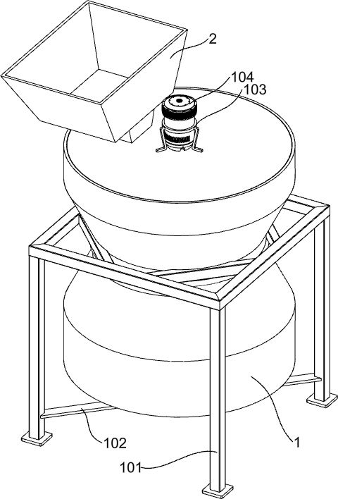
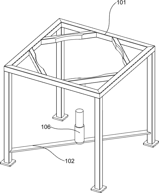
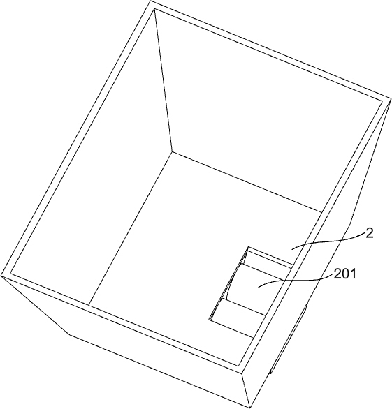
[0035] A continuous drying device for polyester chips, such as Figure 1-10 As shown, it includes a drying bin 1, a fixing frame 101, a fixing rod 102, a supporting frame 103, a power motor 104, a rotating shaft 105, a blanking frame 2 and a drum 201, and a drying bin 1 is fixedly installed in the fixing frame 101. The dry bin 1 is provided with a multi-layer drying structure. After multi-layer rolling and continuous drying treatment, the moisture inside the polyester chips will be completely dried. The bottom of the fixing frame 101 is fixedly connected with a fixing rod 102. The top of the drying bin 1 is The wall is provided with a support frame 103, a power motor 104 is installed in the support frame 103, a rotating shaft 105 is rotatably connected in the drying bin 1, the output shaft of the power motor 104 is connected with the rotating shaft 105, and the power motor 104 drives the drying bin 1 through the rotating shaft 105. The drying structure of each inner layer oper...

Embodiment 2

[0038] On the basis of Example 1, as Figure 4 As shown, it also includes a fixed feeding plate 3, a material pushing slant plate 301, a first connecting ring 302, a flattening stop rod 303 and a first connecting rod 304, and a fixed feeding plate 3 is fixed on the inner top of the drying bin 1, A first connecting ring 302 is rotatably connected to the top of the rotating shaft 105 , a first connecting rod 304 is fixed between the first connecting ring 302 and the drying chamber 1 , and a flattening block 303 is rotatably connected to the first connecting rod 304 , and the top of the rotating shaft 105 A pusher inclined plate 301 is fixed, and the side of the pusher inclined plate 301 in contact with the polyester chips is a vertical wall. The pusher inclined plate 301 pushes the polyester chips to move. The polyester chips will be spread out to a fixed thickness, and finally the polyester chips will be pushed to the rectangular through holes of the fixed feeder plate 3 by the...


PUM


Abstract

The invention discloses a continuous drying device for polyester chips. The continuous drying device comprises a drying bin, a fixing frame, a fixing rod, a supporting frame, a power motor and the like. A fixing rod is fixedly connected to the bottom of the fixing frame, a supporting frame is arranged on the top wall of the drying bin, a power motor is installed in the supporting frame, a rotating shaft is rotationally connected into the drying bin, an output shaft of the power motor is connected with the rotating shaft, and a discharging frame is arranged on the top of the drying bin. The multi-layer drying structure is arranged in the drying bin, the polyester chips are rolled into the small polyester chips from the large bonded polyester chips, meanwhile, the polyester chips are continuously dried, water in the polyester chips is completely evaporated, and the drying efficiency is improved. And treating the moistened and bonded polyester chips into dry and mutually dispersed polyester chip particles.

Description

technical field [0001] The invention relates to the field of polyester chip processing, in particular to a continuous drying device for polyester chips. Background technique [0002] Polyester chips usually refer to the polyester raw materials produced by polymerization are generally processed into flake particles of about 4*5*2 mm. The technical route of polyester production includes direct esterification method (PTA method) and transesterification method (DMT method). As a hydrophilic material, polyester chips are easy to cause yarn ends or wool when using water-containing chips to make spinning threads, which affects normal production. Therefore, the raw materials of polyester chips need to be dried to remove polystyrene. Moisture in ester chips. [0003] Chinese patent CN212158060U discloses a continuous drying device for polyester chips, which includes a blower, an exhaust nozzle, a slag discharge nozzle, an electric heating wire, an air duct, a screen, a guard plate ...

Claims


Application Information

Patent Timeline
IPC IPC(8): B29B13/06B29B13/10
CPCB29B13/06B29B13/10Y02W30/62
Inventor 王果连靖永春闫向红王会军王洋郭文光
Owner 河南源宏高分子新材料有限公司
Why Eureka
Try Eureka