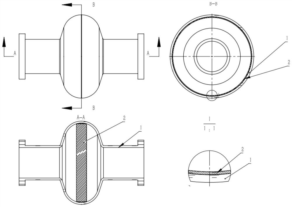
Microwave resonant cavity
A microwave resonator, resonator technology, applied in resonators, waveguide devices, cooling/ventilation/heating transformation, etc., can solve the problem of improving the performance of the resonator without a system, the bottleneck of the performance of the resonator, and the mechanical strength should not be too low, etc. problems, to achieve the effect of improving operating stability, reducing the maximum temperature rise, and reducing the positive feedback effect
- Summary
- Abstract
- Description
- Claims
- Application Information
AI Technical Summary
Problems solved by technology
Method used
Image
Examples
Embodiment 1
[0026] Example 1. Microwave resonant cavity
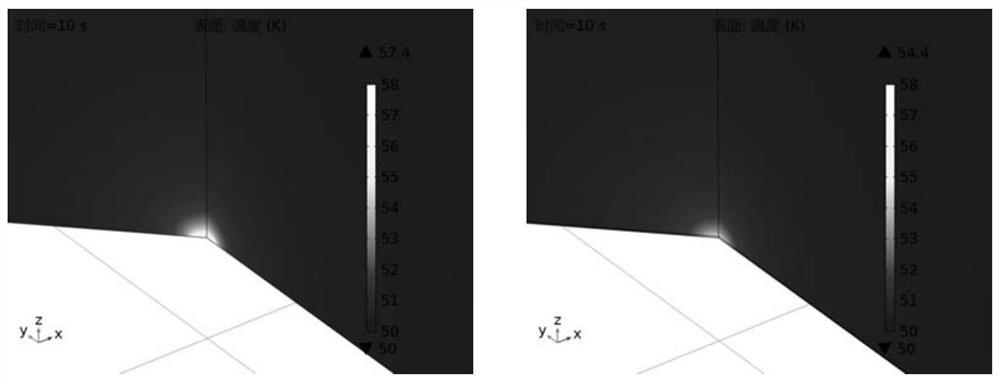
[0027] Use COMSOL to simulate the influence of the thermal conductive film: select the cavity material as copper (RRR value is 30), use the COMSOL material library with its own thermal conductivity (Copper[solid,residual resistivity ratio of 30]), set the cavity wall thickness to 1mm, and set the wall thickness to 1mm. The outer boundary cooling temperature is 50K. Select a disc-shaped local area with a radius of 0.1 cm, and set a disc-shaped constant-power heat source in the center of the inner surface, and its power is 10 16 W / m 3 , the radius is 0.01mm, and the thickness is 50nm. The simulation results show that the maximum temperature in the center of the model at steady state (after 10 seconds) is 57.4K.
[0028] A thermal conductive layer coating with a thickness of 1 μm is added to the inner wall, the material is SiC, and the thermal conductivity is selected from the literature [DonaldT.Morelli, G.A.S., High Lattice Therm...
Embodiment 2
[0029] Example 2, microwave resonant cavity
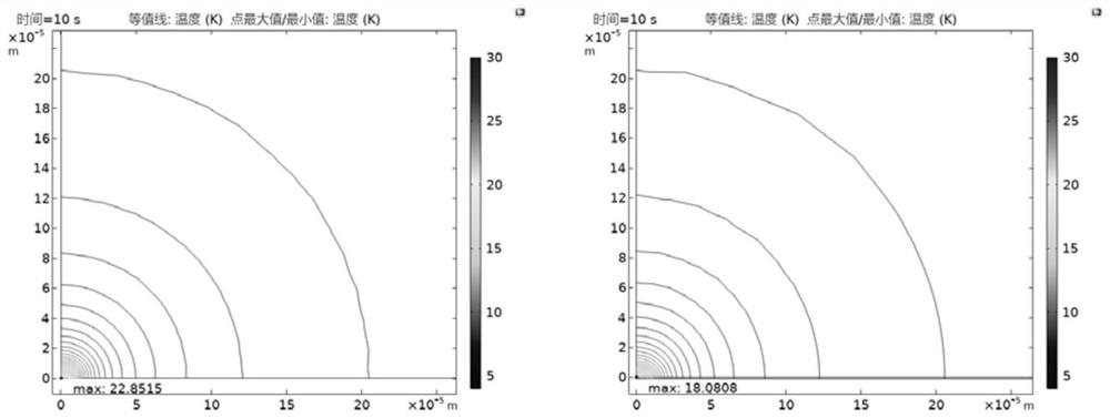
[0030] Use COMSOL to simulate the influence of the thermal conductive film: select the cavity material as niobium, use the built-in thermal conductivity (Nb[Solidpolycrystalline]) of the COMSOL material library, set the thickness of the cavity wall to 1mm, and set the cooling temperature of the outer boundary of the wall to 4K. Select a disc-shaped local area with a radius of 0.1 cm, and set a disc-shaped constant-power heat source in the center of the inner surface, and its power is 10 16 W / m 3 , the radius is 0.01mm, and the thickness is 50nm. The simulation results show that the maximum temperature in the center of the model at steady state (after 10 seconds) is 22.9K.
[0031]Add a thermal conductive layer coating with a thickness of 1 μm to the inner wall, the material is AlN, the thermal conductivity above 15K is COMSOL default, and the thermal conductivity below 15K is selected from the literature [Donald T.Morelli, G.A.S....
Embodiment 3
[0032] Example 3, microwave resonant cavity
[0033] Use COMSOL to simulate the influence of the thermal conductive film: select the cavity material as niobium plated with niobium tri-tin, niobium uses the COMSOL material library with its own thermal conductivity (Nb[Solid, polycrystalline]), set the niobium thickness of the cavity wall to 1mm, and the niobium tri-tin layer Thickness of 2 μm, thermal conductivity of niobium tritin from literature [Andries den Ouden, H.H.J.t.K., Thermal conductivity of mica / glass insulation for impregnated Nb3Sn windings in accelerator magnets. Cryogenics, 1994.34(1):p.385-388], wall outer boundary cooling temperature to 4K. Select a disc-shaped local area with a radius of 0.1 cm, and set a disc-shaped constant-power heat source in the center of the inner surface, and its power is 10 13 W / m 3 , the radius is 0.01mm, and the thickness is 50nm. The simulation results show that the maximum temperature in the center of the model at steady state ...
PUM
| Property | Measurement | Unit |
|---|---|---|
| Thickness | aaaaa | aaaaa |
| Thermal conductivity | aaaaa | aaaaa |
| Thickness | aaaaa | aaaaa |
Abstract
Description
Claims
Application Information
 - R&D
- Intellectual Property
- Life Sciences
- Materials
- Tech Scout
- Unparalleled Data Quality
- Higher Quality Content
- 60% Fewer Hallucinations
Browse by: Latest US Patents, China's latest patents, Technical Efficacy Thesaurus, Application Domain, Technology Topic, Popular Technical Reports.
© 2025 PatSnap. All rights reserved.Legal|Privacy policy|Modern Slavery Act Transparency Statement|Sitemap|About US| Contact US: help@patsnap.com


