Sealed liquid ammonia pump for conveying liquid ammonia
A sealed and liquid ammonia technology, which is applied in the field of liquid ammonia pumps, can solve the problems of reduced service life of liquid ammonia pumps, increased pump internal pressure, and easy damage to internal parts, so as to reduce environmental requirements, prolong service life, and improve The effect of the cooling effect
- Summary
- Abstract
- Description
- Claims
- Application Information
AI Technical Summary
Problems solved by technology
Method used
Image

Examples
Embodiment 1
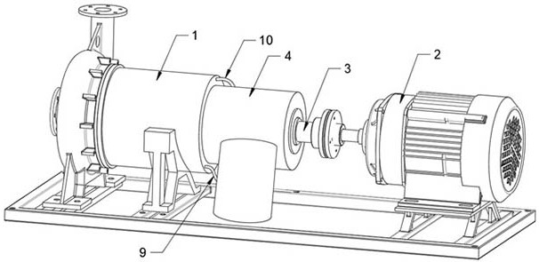
[0027] Example one, as Figure 1 to Figure 6As shown, a sealed liquid ammonia pump for liquid ammonia transportation includes a magnetic pump housing 1 and a motor 2. The output shaft of the motor 2 is connected to the main shaft 3 in the magnetic pump housing 1. Due to the particularity of liquid ammonia, It is necessary to use a liquid ammonia pump with strong airtightness to transport liquid ammonia. Therefore, a magnetic pump is used to transport liquid ammonia. The magnetic pump couples the inner magnetic rotor connected to the impeller to rotate synchronously through the action of magnetic lines of force, and realizes the torque The non-contact transmission, from the original conventional pump with a shaft seal on one shaft to two shafts with an isolation sleeve structure, converts the dynamic seal into a static seal, thus completely solving the problem of medium leakage, with super strong The tightness of the liquid ammonia meets the transportation requirements of liqui...
Embodiment 2
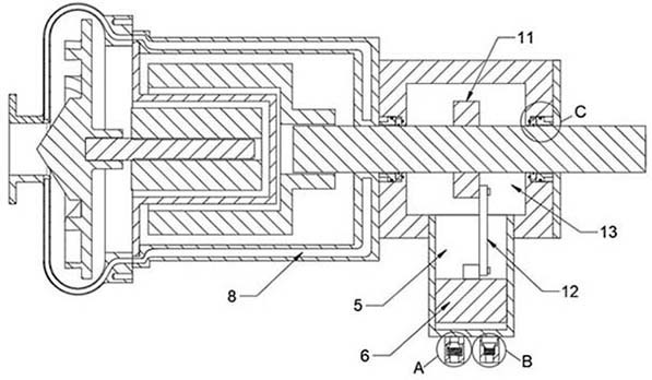
[0029] Embodiment 2, on the basis of embodiment 1, further, as image 3 and Figure 4 As shown, the cooling housing 4 is connected with an oil inlet pipe 14 and an oil return pipe 15 at the end of the piston chamber 5 away from the main shaft 3. The oil inlet pipe 14 and the oil return pipe 15 are respectively connected to the oil inlet hose 9 and the oil return hose 10. The oil return pipe 15 and the oil inlet pipe 14 are respectively provided with a one-way oil return valve 16 and a one-way oil inlet valve 17. When the one-way oil inlet valve 17 is turned on, the one-way oil return valve 16 is closed, and when the one-way oil return valve 16 leads When it is on, the one-way oil inlet valve 17 is closed, and the one-way oil return valve 16 and the one-way oil inlet valve 17 are both closed under normal conditions. When the piston 6 moves away from the main shaft 3, under the action of the pressure difference, the one-way oil The oil inlet valve 17 is automatically turned on,...
Embodiment 3
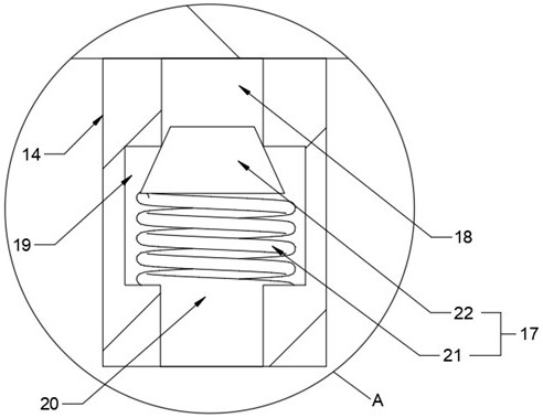
[0032] Embodiment 3, on the basis of embodiment 2, further, as figure 2 and Image 6 As shown, the piston chamber 5 is located below the driving chamber 13, so that the cooling oil in the piston chamber 5 cannot easily leak into the driving chamber 13 under the action of gravity. When sliding in the piston cavity 5, a gap will inevitably occur, and a small amount of overflow occurs. Therefore, on this basis, a sealing component is also provided at the connection between the cooling shell 4 and the main shaft 3 to prevent the leakage of cooling oil. Therefore, both ends of the cooling casing 4 along the axial direction of the main shaft 3 are provided with sealing grooves 32 , the axis of the sealing groove 32 is parallel to the axis of the driving cavity 13 , the diameter of the sealing groove 32 is larger than that of the driving cavity 13 , and the inner diameter of the sealing groove 32 is larger than that of the driving cavity 13 . A sealing assembly is provided. The sea...
PUM
 Abstract
Description
Claims
Application Information
 - Generate Ideas
- Intellectual Property
- Life Sciences
- Materials
- Tech Scout
- Unparalleled Data Quality
- Higher Quality Content
- 60% Fewer Hallucinations
Browse by: Latest US Patents, China's latest patents, Technical Efficacy Thesaurus, Application Domain, Technology Topic, Popular Technical Reports.
© 2025 PatSnap. All rights reserved.Legal|Privacy policy|Modern Slavery Act Transparency Statement|Sitemap|About US| Contact US: help@patsnap.com