Pressure measurement system and method based on optical fiber
A measurement system and pressure technology, applied in the field of optical fiber-based pressure measurement systems, can solve the problems of complex process and assembly, high processing cost, poor mechanical properties, etc. Effect
- Summary
- Abstract
- Description
- Claims
- Application Information
AI Technical Summary
Problems solved by technology
Method used
Image
Examples
Embodiment 1
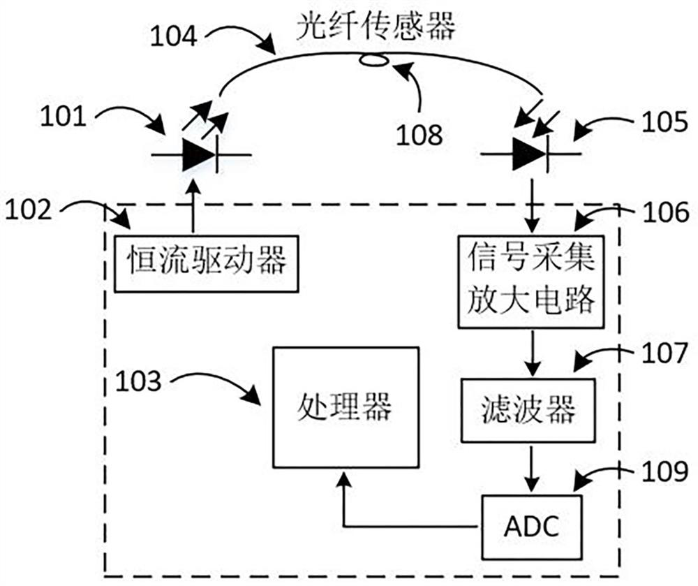
[0075] see figure 1 , an optical fiber-based pressure measurement system comprising:
[0076] The light source 101 adopts a narrow-band infrared LED; the constant current driver 102, the optical fiber sensor 104, and the optical fiber sensor 104 surrounds an optical fiber ring 108 with a radius of 1 mm, so that the curvature of the optical fiber changes, and is cured in the flexible material silica gel, when the light passes through the optical fiber When the ring 108 is placed, part of the light is refracted out of the optical fiber and lost, the photodiode 105, the signal acquisition and amplification circuit 106, the filter 107, the analog-to-digital converter 109, the analog-to-digital converter 109 is an ADC, and the processor 103;
[0077] The constant current driver 102, the light source 101, the optical fiber sensor 104, the photodiode 105, the signal acquisition and amplification circuit 106, the filter 107, the ADC 109, and the processor 103 are sequentially connecte...
Embodiment 2
[0091] see Figure 4 , an optical fiber-based pressure measurement system comprising:
[0092] The light source 401, the constant current driver 402, the first fiber sensor 404 and the second fiber sensor 405 are used as fiber sensors. The axes of the first fiber sensor 404 and the second fiber sensor 405 are perpendicular to each other, that is, the first fiber sensor 404 and the second fiber The optical fiber ring 411 wound by the sensor 405 is enveloped into a spherical surface, and is cured together with a flexible material such as silica gel. The first photodiode 406 and the second photodiode 407 are used to measure the output light intensity of the optical fiber ring 411. Filter 409, analog-to-digital converter 410 is ADC, processor 403;
[0093] Step S1: the illumination light emitted by the light source 401 is transmitted to the first photodiode 406 and the second photodiode 407 through the first optical fiber sensor 404 and the second optical fiber sensor 405, respec...
Embodiment 3
[0103] see Figure 5 , In many application scenarios, it is often necessary to measure the pressure distribution of a plane, such as the foot pressure distribution of a biped robot or the manipulator of a robot to judge the surface of a rigid object. At this time, the fiber optic sensor can easily form a sensor matrix to measure the sensor matrix. pressure distribution on.
[0104] An optical fiber-based pressure measurement system comprising:
[0105] A plurality of light sources 501, and the light sources 501 are infrared LEDs, a constant current driver 502, and a sensor matrix composed of 4*4 fiber optic sensors 503, used to measure pressure distribution or rigid body edges, each light source 501 corresponds to a fiber optic sensor 503, each The optical fiber sensors 503 are all wound with optical fiber rings and photodiodes 504. Each optical fiber sensor 503 corresponds to a photodiode 504. The signal acquisition and processing circuit 505 includes a signal acquisition and ...
PUM
 Abstract
Description
Claims
Application Information
 - R&D
- Intellectual Property
- Life Sciences
- Materials
- Tech Scout
- Unparalleled Data Quality
- Higher Quality Content
- 60% Fewer Hallucinations
Browse by: Latest US Patents, China's latest patents, Technical Efficacy Thesaurus, Application Domain, Technology Topic, Popular Technical Reports.
© 2025 PatSnap. All rights reserved.Legal|Privacy policy|Modern Slavery Act Transparency Statement|Sitemap|About US| Contact US: help@patsnap.com


