Flue gas denitration device for solid waste treatment

A denitrification and flue gas technology, applied in the field of flue gas denitrification, can solve the problems of insufficient gas reaction, inability to remove soot particles, and insufficient denitration, etc., to achieve the effect of easy inflow treatment, convenient centralized treatment, and good gas treatment effect

Inactive Publication Date: 2022-08-05
王成
View PDF1 Cites 0 Cited by
  • Summary
  • Abstract
  • Description
  • Claims
  • Application Information

AI Technical Summary

Problems solved by technology

[0004] In the above public documents, during the gas treatment process, the soot particles in the gas cannot be removed, resulting in insufficient denitrification of the gas during the denitrification process; on the other hand, the time of the gas in the denitrification tower is relatively short, and There is a denitration agent spraying device on one side of the board, which makes the gas reaction not sufficient, low working efficiency and poor effect

Method used


Image

  • Flue gas denitration device for solid waste treatment
  • Flue gas denitration device for solid waste treatment
  • Flue gas denitration device for solid waste treatment

Examples


Embodiment 1

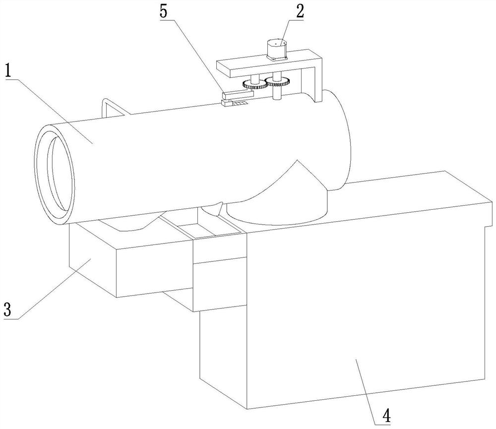
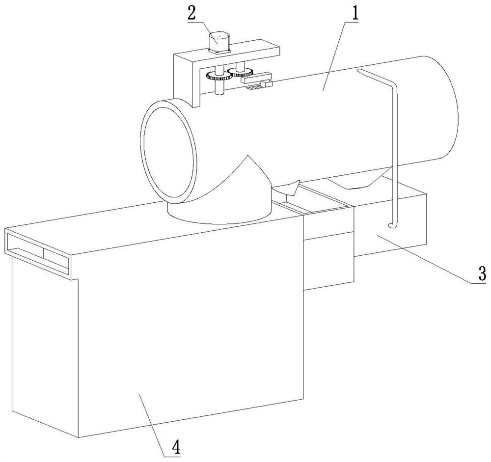
[0032] A flue gas denitration device for solid waste treatment proposed by the present invention includes an air intake assembly 1 and a denitration assembly 4;

[0033] like Figure 1-2 As shown, the denitration assembly 4 is provided with an air intake assembly 1, and the air intake assembly 1 is provided with a circulating dust removal assembly 3 for treating smoke and dust in the gas;

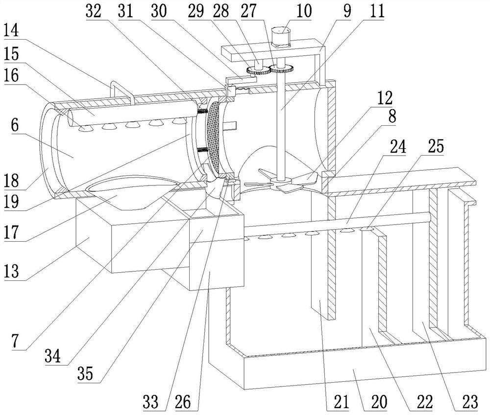
[0034] like image 3 As shown, the intake assembly 1 includes an intake pipe 6 and a connecting pipe 8; the intake pipe 6 is communicated with the denitration tank 20 through the connecting pipe 8, and the intake pipe 6 is provided with a filter screen 7; the intake pipe 6 is provided with a leak-proof ring A18 and the leak-proof ring B19, and the leak-proof ring A18 and the leak-proof ring B19 are respectively located on both sides of the dirt collecting hopper A17; the cross-section of the leak-proof ring A18 is an isosceles triangle, and the cross-sectional area of ​​the leak-proof ring...

Embodiment 2

[0039] like Figure 1-3 As shown in the figure, a flue gas denitrification device for solid waste treatment proposed by the present invention, compared with the first embodiment, the difference in this embodiment is that the air intake assembly 1 is further provided with an automatic cleaning assembly 5, wherein the automatic cleaning assembly 5 It includes gear A27, rotating shaft B28, gear B29, reciprocating connecting rod 30, slider 31, movable ring 33, dirt collecting bucket B34, and dirt collecting box 35; The sliding block 31 is slidably arranged on the intake pipe 6, and the two ends of the reciprocating connecting rod 30 are respectively connected with the sliding block 31 and the gear B29 through the rotating column in rotation; The connection is not at the axis of the gear B29; the movable ring 33 is slidably arranged on the intake pipe 6 and connected with the slider 31; the intake pipe 6 is provided with a pleated sealing cloth, and the pleated sealing cloth is con...


PUM


Abstract

The invention relates to the technical field of flue gas denitration, in particular to a flue gas denitration device for solid waste treatment. The device comprises a gas inlet assembly and a denitration assembly, a gas inlet assembly is arranged on the denitration assembly, and a circulating dust removal assembly is arranged on the gas inlet assembly; the gas inlet pipe is communicated with the denitration box through a connecting pipe; a filter screen is arranged on the gas inlet pipe; the partition plate A and the partition plate C are arranged at the top of the denitration box and have gaps with the bottom; the partition plate B is arranged at the bottom of the denitration box and has a gap with the top; the liquid medicine box is arranged on the denitration box, the medicine distribution pipe is arranged on the sub partition plate C and penetrates through the partition plate B and the partition plate A to be communicated with the liquid medicine box, and the medicine distribution pipe is provided with an atomization nozzle B; the water distribution pipe is arranged on the air inlet pipe and is provided with an atomizing nozzle A; the circulating pipe is arranged on the treatment water tank and is communicated with the water distribution pipe; the dirt collecting hopper A is arranged on the air inlet pipe and is communicated with the treatment water tank. The device is more energy-saving and environment-friendly, the gas treatment time is long, the denitration is sufficient, and the working efficiency is improved.

Description

technical field [0001] The invention relates to the technical field of flue gas denitration, in particular to a flue gas denitration device for solid waste treatment. Background technique [0002] In the treatment of solid waste, the pulverized solid material is usually burned and cracked by a rotary kiln to decompose it into water, oil and gas. However, the generated waste gas needs to be treated and can be discharged only after reaching the national emission standard. [0003] The Chinese patent publication number CN213221597U discloses a flue gas denitrification device for a solid waste treatment system. The solid waste treatment system includes a rotary kiln, a secondary combustion chamber and a quenching tower connected in sequence. A flue gas denitrification tower is connected in series between them. The flue gas denitrification tower includes a tower body, a urea distribution mechanism and an atomizing spray gun. The reaction chamber and the cooling chamber are conn...

Claims


Application Information

Patent Timeline
Patent Type & Authority Applications(China)
IPC IPC(8): B01D50/60B01D53/56B01D53/79
CPCB01D50/60B01D53/56B01D53/79Y02A50/20
Inventor 王成王博刘茂干
Owner 王成
Why Eureka
Try Eureka