
Automatic device and method for verifying accuracy of vertical line system

An automatic device and technology of accuracy, applied in the direction of using mechanical devices, measuring devices, mechanical measuring devices, etc., can solve the problems of unconsidered, inconvenient on-site testing, and high requirements for operators and on-site conditions, and achieves guaranteed range of activities and range. , The overall structure is compact and compact, and the effect of automatic calibration is realized.

Pending Publication Date: 2022-08-05
XIAN THERMAL POWER RES INST CO LTD +2
View PDF1 Cites 0 Cited by
  • Summary
  • Abstract
  • Description
  • Claims
  • Application Information

AI Technical Summary

Problems solved by technology

[0004] First, the prior art uses a vertical line calibration frame combined with a standard gauge block or a dial indicator, which is assembled with a magnetic base and fixed on the steel frame of the vertical line coordinate instrument. This assembly and fixing method is complicated and stable. Poor, it is very easy to cause the overall sliding during the test process, and the abnormal displacement caused by touching the vertical line body. Second, during the test process, the direction of the given displacement is only adjusted by the on-site personnel through visual inspection, and there is a large deviation from the actual direction of the X-axis and Y-axis of the telemetry vertical line coordinate instrument, which cannot achieve accurate Orientation, but cannot guarantee that the plane where the two axes of the given displacement are located is parallel to the plane composed of the two directions calibrated by the telemetry vertical line coordinate instrument, which will inevitably bring about a certain systematic error; third, the accuracy test of the vertical line system It is necessary to verify the accuracy of the measured values ​​in the four directions of the two coordinate axes of the left and right bank directions and the upstream and downstream directions. When converting the measurement coordinate axes, the existing technology needs to select a suitable position for the vertical line calibration frame, dial indicator and other equipment. It is laborious and inefficient to reassemble and arrange through the magnetic table base; in addition, in some on-site conditions, the test device can only be arranged in one direction, and the test cannot be carried out in the other direction; fourth, the existing device is vulnerable to telemetry vertical coordinate instrument Influenced by the on-site layout of the fixed steel frame, when the space between the steel frame and the vertical coordinate instrument is limited, the test device cannot be arranged, which is inconvenient for on-site testing. In this case, the test device can only be installed on the fixed steel frame The top or other remote parts of the vertical line system lead to a certain distance between the given displacement point and the monitoring point of the telemetry vertical line coordinate instrument, resulting in a linear error; fifth, there is no unified process for the accuracy test method of the vertical line system at present, and evaluation Most of the methods only use the difference between the data collected by the automation system and the given displacement in the field to compare and judge. In the case of a large absolute value of the deviation, it is impossible to distinguish the defects of the telemetry vertical line coordinate instrument, the acquisition module or the automation system.
[0005] Chinese patent, notification number CN203672345 U, discloses a universal calibration frame for on-site testing of the accuracy of the vertical line coordinate instrument of a hydropower station. This device only improves the applicability of the fixed installation base, and integrates the calibration frame with the displacement measuring device, reducing The error caused by the separate fixing of the calibration frame and the dial indicator does not consider the abnormalities caused by various factors such as the disturbance of the vertical line body, the accuracy of the given displacement, the synchronization of the moving direction, and the deviation of the displacement point. The error problem has not been considered, and how to improve the conversion efficiency of the measurement coordinate axis and standardize the measurement method have not been considered.

Method used


Image

  • Automatic device and method for verifying accuracy of vertical line system
  • Automatic device and method for verifying accuracy of vertical line system
  • Automatic device and method for verifying accuracy of vertical line system

Examples


Embodiment Construction

[0040] The present invention is described in detail below, so that the advantages and features of the present invention can be more easily understood by those skilled in the art, and the protection scope of the present invention can be more clearly defined.

[0041] A brief summary of one or more aspects is presented below to provide a basic understanding of the aspects. This summary is not an exhaustive overview of all contemplated aspects and is neither intended to identify key or critical elements of all aspects nor attempt to delineate the scope of any or all aspects. Its sole purpose is to present some concepts of one or more aspects in a simplified form as a prelude to the more detailed description that is presented later.

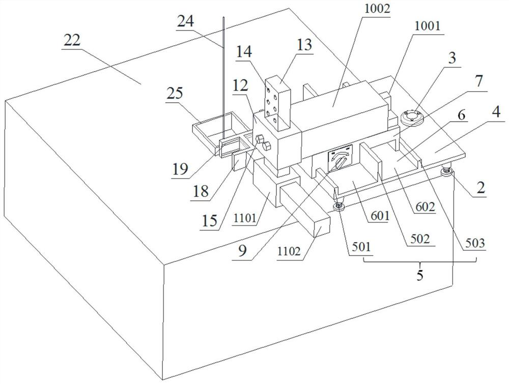
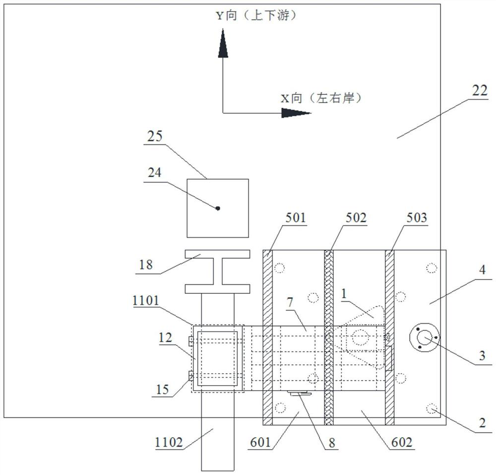
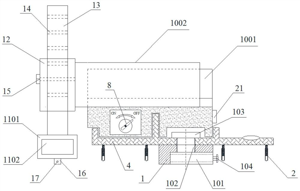
[0042] like Figure 1-6 As shown in the figure, an automatic device for the accuracy verification of the vertical line system includes a triangular base 1, a work table 4, a linear slide rail 5, a guide groove 6, a slider 7, an X-direction linear mo...


PUM


Abstract

The invention discloses an automation device and method for verifying the accuracy of a vertical line system, and the device comprises a working platen, the working platen is disposed on a vertical line coordinatograph, the working platen is provided with a guide groove, the guide groove is internally provided with a sliding block, the sliding block is provided with a motor I, the end part of the motor I is provided with a strip-shaped measuring rod, and the lower part of the strip-shaped measuring rod is provided with a motor II. A laser is arranged at the bottom of the motor II, and an H-shaped wire contact mechanism is arranged at the end of the motor II and works cooperatively with the motor I and the motor II, so that accurate displacement is given to the vertical line in the verification process. The working platen can be horizontally and stably placed at any position, the laser can be adopted for precise orientation, the consistency of the moving direction and the plumb line coordinatograph is guaranteed, the linear motor is adopted for eliminating positioning errors, the H-shaped line contact mechanism is adopted for guaranteeing zero disturbance of the initial value of a plumb line, the overall structure is compact and small, applicability is high, and adjustment and control are easy. The working process is simple and clear, the working efficiency is improved, and automatic verification of the accuracy of the vertical line system is realized.

Description

technical field [0001] The invention belongs to the technical field of dam safety monitoring system testing and evaluation, and in particular relates to an automatic device and method for calibrating the accuracy of a vertical line system. Background technique [0002] As the most accurate and effective means of deformation monitoring in the horizontal direction, the vertical line system is based on the vertical steel wire. The most important monitoring facility for horizontal displacement and deflection of hydraulic structures plays an important role in grasping the operational behavior of the dam structure and discovering the risks and hidden dangers of hydraulic structures. However, in the actual operation process, due to various factors such as human disturbance, changes in environmental factors, incorrect parameter settings, monitoring equipment aging, and sensor damage, the vertical system often results in inaccurate monitoring results and data distortion. In order to...

Claims


Application Information

Patent Timeline
IPC IPC(8): G01B5/30G01B5/02G01B5/00G01C15/00
CPCG01B5/30G01B5/02G01B5/0002G01B5/0004G01B21/042G01C15/002Y02P90/02
Inventor 程帅南江汪俊波裴海林马优彭金宁陈少华张世明杨光曹一凡申一洲李波
Owner XIAN THERMAL POWER RES INST CO LTD
Learn More