Optical fibre prefab manufacture and device thereof

A technology of optical fiber prefabrication and airflow, applied in the direction of manufacturing tools, optical components, glass manufacturing equipment, etc., to achieve the effects of avoiding cracking, uniform growth, and stable temperature

Inactive Publication Date: 2005-11-02
HANGZHOU FUTONG COMM TECH CO LTD
View PDF0 Cites 0 Cited by
  • Summary
  • Abstract
  • Description
  • Claims
  • Application Information

AI Technical Summary

Problems solved by technology

[0007] The technical problem to be solved and the technical task proposed by the present invention are to overcome the technical defects existing in the manufacturing process of the existing optical fiber preform, and provide a method and device for manufacturing an optical fiber preform that can adjust the airflow in the reaction vessel to ensure During the entire deposition process, the pressure and gas flow in the reaction vessel are basically stable, and the undeposited SiO is discharged in time 2 、GeO 2 Particles can effectively reduce the temperature fluctuation in the reaction vessel and the uneven growth of the optical fiber preform, and further increase the effective length of the optical fiber preform and improve its raw material utilization

Method used


Image

  • Optical fibre prefab manufacture and device thereof
  • Optical fibre prefab manufacture and device thereof
  • Optical fibre prefab manufacture and device thereof

Examples


Embodiment 1

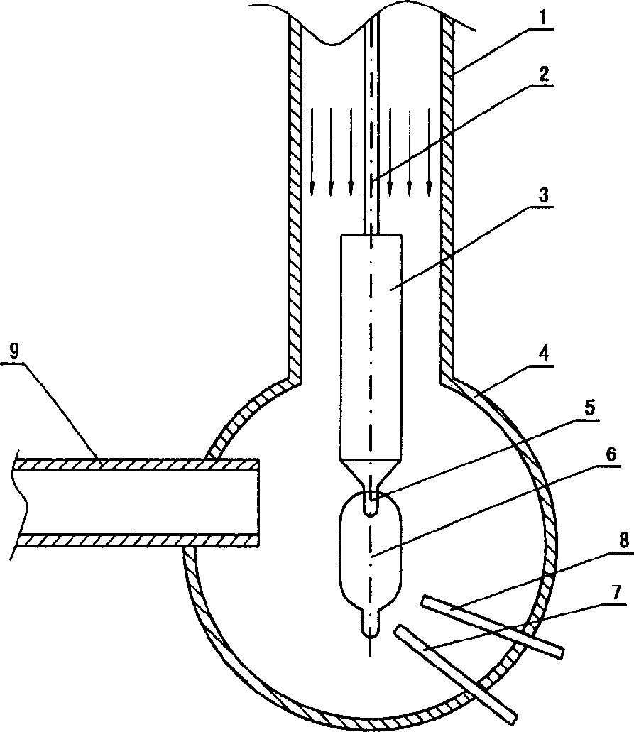
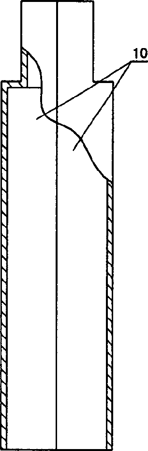
[0036] Embodiment one: in the case of the exhaust port 9 exhaust, the seed rod 5 with a diameter of 25 mm is installed and hung on the sliding sleeve 16 with the first screw 12, and then the air flow with a diameter of 145 mm is connected with the second screw 13. The rectifier 3 is also installed and hung on the sliding sleeve 16, and then the seed rod 5 and the gas rectifier 3 are inserted into the spherical reaction vessel 4 from the air inlet at the upper end of the flange pipe 1 with an internal diameter of 250mm, and the lower end of the seed rod 5 Corresponding to the two spray guns, the seed rod is lifted by the uniform rotation of the lead rod, the exhaust port 9 is connected with the exhaust fan, and the pressure is controlled at about 100Pa, and the exhaust is started; The pressure is about 2.0×10 5 Pa, the air rectification air flow with a temperature of about 20°C; then feed hydrogen and oxygen into the two spray guns, and ignite a hydrogen-oxygen flame at about 1...

Embodiment 2

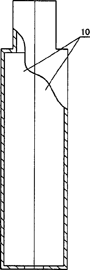
[0038] Embodiment 2: The difference from Embodiment 1 is that the pressure is about 2.0×10 from the air inlet on the upper end of the flange pipe into the reaction vessel. 5 Nitrogen rectified airflow heated to 200°C in Pa; the reaction is carried out in a balanced state for a certain period of time to obtain the predetermined optical fiber preform; since the rectified airflow is selected from the heated inert gas, it is compatible with the reaction vessel The temperature difference of the gas is smaller, which can better keep the temperature in the reaction vessel stable, and the reaction effect is better.

[0039] In the case of using an inert gas for the rectified gas flow, it is mainly because the stability of the inert gas is good, which can better ensure the stability of the reaction process.

[0040] For the three gases used to rectify the airflow, their temperature and pressure can be selected according to actual needs.

[0041] It should be noted that during the manu...


PUM


Abstract

A process and equipment for preparing the prefabricated body of optical fibre is disclosed. A seed rod is put in reacting container via frange tube to make it opposite to spray gun. A cylindrical fairing body is linked to said seed rod in such manner that the lower end of fairing body is near the lower end of seed rod. A gas flow is introduced in from said frange tube, flows through the gap between said seed rod and fairing body, and finally is exhausted. It can stabilize the pressure in reacting container and carry out the microparticles of SiO2 and GeO2.

Description

【Technical field】 [0001] The invention relates to a method and device for manufacturing an optical fiber preform, which belongs to the field of optical fiber manufacturing. 【Background technique】 [0002] Inorganic optical fibers have been widely used in the communication industry, among which quartz-based optical fibers have become the leading inorganic optical fibers due to their advantages such as low optical loss, wide range of applicable light waves, and adaptability to long-distance communication. Among the methods for manufacturing quartz-based optical fiber preforms, there is a vapor phase axial deposition method (VAD method). The manufacturing device it uses includes a reaction vessel with an exhaust port. A spray gun with a mouth, and a seed rod is vertically arranged in the reaction vessel. When manufacturing optical fiber preforms, place the seed rod vertically in the reaction vessel corresponding to the spray gun, pass hydrogen and oxygen into the spray gun and...

Claims


Application Information

Patent Timeline
Patent Type & Authority Patents(China)
IPC IPC(8): C03B37/012C03B37/014C03B37/018G02B6/00
CPCC03B37/01486Y02P40/57
Inventor 羊荣金曹松峰吴兴坤儿玉喜直山本岳彦
Owner HANGZHOU FUTONG COMM TECH CO LTD
Why Eureka
Try Eureka