Method for detecting organic molecule in solution by nano material catalytic light emitting and detector

A nano-material and luminescence detection technology, which is applied in the field of nano-material catalytic luminescence detection of organic molecules in solution, to achieve the effects of easy operation, good repeatability and long life

Inactive Publication Date: 2006-03-22
TSINGHUA UNIV
View PDF0 Cites 0 Cited by
  • Summary
  • Abstract
  • Description
  • Claims
  • Application Information

AI Technical Summary

Problems solved by technology

Literature search found that the use of nanomaterials to achieve the determination of organic molecules in solution has not been reported.

Method used


Image

  • Method for detecting organic molecule in solution by nano material catalytic light emitting and detector
  • Method for detecting organic molecule in solution by nano material catalytic light emitting and detector

Examples


Embodiment 1

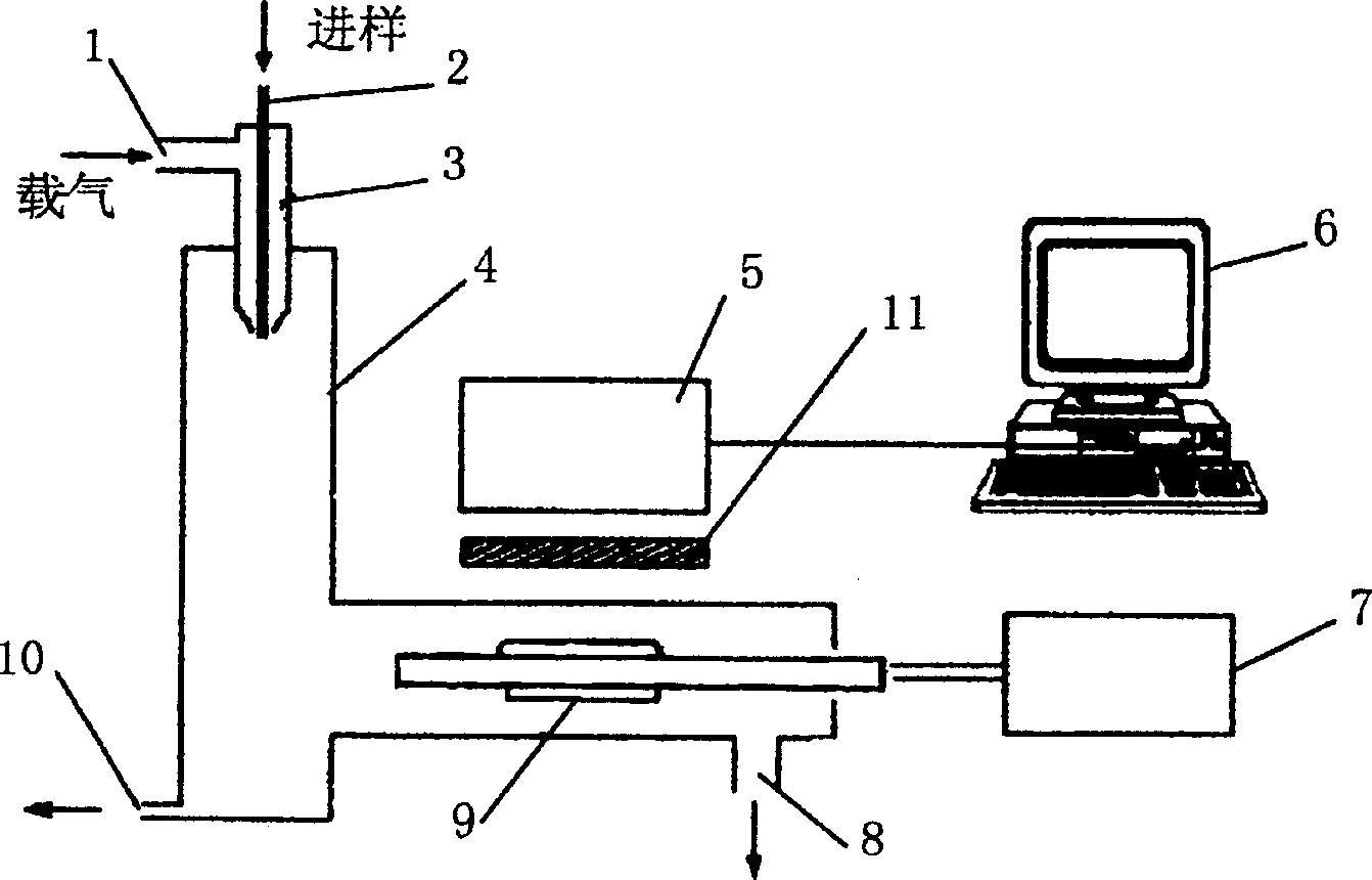
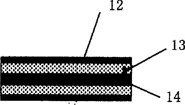
[0010] Embodiment one: the nanomaterial γ-Al 2 o 3 It is coated or sintered on the surface of the ceramic heater in the form of powder or film, and the temperature is raised to 500°C and kept for 30 minutes to eliminate the interference of adsorbate. The working temperature is 100°C, and the carrier gas is N 2 :O 2 Mixed gas (ratio in the range of 1:99-99:1), the flow rate is 10L / min, and the detection wavelength can be changed from 400-700nm. Take a quantitative sample solution, such as 50 μL of sucrose or glucose or other sugar compound aqueous solution, inject it into the detector from the injection port, the test solution is atomized and brought to the catalytic luminescent device for reaction, and the optical signal is detected by the photomultiplier tube , the computer automatically collects the signal. The optical signal changes linearly with the concentration of the solution. For example, for sucrose solution, the linear range is 10-1000μg / mL; for glucose solution,...

Embodiment 2

[0011] Embodiment two: the nanomaterial SrCO 3 It is sintered on the surface of the ceramic heater in the form of powder or film, and the temperature is raised to 500°C and kept for 30 minutes to eliminate the interference of adsorbate. The working temperature is 30°C, and the carrier gas is N 2 :O 2 Mixed gas (ratio in the range of 1:99-99:1), the flow rate is 0.5L / min, and the detection wavelength can be changed from 400-700nm. Take a quantitative solution, such as 50 μL of ethanol and other alcohol compound solutions, inject it into the detector through the injection port, the test solution is atomized and brought to the catalytic luminescent reaction device for reaction, the optical signal is detected by the photomultiplier tube, and the computer The signal is collected automatically, and the optical signal changes linearly with the concentration of the solution. For example, for ethanol solution, the linear range is 10-1000μg / mL.

Embodiment 3

[0012] Example three: the nanomaterial γ-Al 2 o 3 It is sintered on the surface of the ceramic heater in the form of powder or film, and the temperature is raised to 500°C and kept for 30 minutes to eliminate the interference of adsorbate. The working temperature is 250°C, and the carrier gas is N 2 :O 2 Mixed gas (ratio in the range of 1:99-99:1), the flow rate is 15L / min, and the detection wavelength can be changed from 400-700nm. Take a quantitative sample solution, such as 50 μL of valine or other amino acid compound aqueous solution, inject it into the detector from the injection port, the test solution is atomized and brought to the catalytic luminescent device for reaction, and the optical signal is detected by the photomultiplier tube , the computer automatically collects the signal. The optical signal changes linearly with the concentration of the solution, such as for valine solution, the linear range is 20-1000μg / mL.


PUM


Abstract

The present invention relates to organic material detecting technology. The nano material catalyzed light emitting detecting device includes sample solution atomizer fixed on the top of the aerosol transmitting unit, catalytic light emitting reactor made of nano functional material set inside the horizontal pipe of the aerosol transmitting unit and connected to the temperature controller, and photoelectronic detector with output connected with data processing system. The method of detecting organic molecule in solution is based on the micro atomizing and the nano material catalyzing of organic molecule to emit light. The sample solution is atomized, transmitted and catalytically light emitted during the detection of the organic molecules including those with no or weak ultraviolet absorption. The present invention has no reagent loss, long service life, high sensitivity and other advantages and may be used as one new measure for efficient liquid phase chromatographic analysis.

Description

technical field [0001] The invention belongs to the technical field of chemical material detection, and in particular relates to a method and a detector for detecting organic molecules in a solution by catalytic luminescence of a nanometer material. Background technique [0002] At present, the ultraviolet detector (UVD) in high performance liquid chromatography is a relatively general detector, but the substances it can detect must have chromophores that absorb ultraviolet light, which greatly limits its application range. For the detection of organic compounds with no or weak ultraviolet absorption, differential detectors (RID) and evaporative light detectors (ELSD) are often used, but differential detectors are not suitable for their applications due to their harsh working environment and low sensitivity. It is greatly limited; evaporative photodetectors have not been popularized because of their complex structure, generally low sensitivity and high price. Recently, Japa...

Claims


Application Information

Patent Timeline
Patent Type & Authority Patents(China)
IPC IPC(8): G01N21/62
Inventor 张新荣吕弋刘国宏
Owner TSINGHUA UNIV
Why Eureka
Try Eureka