Integrated residua upgrading and fluid catalytic cracking

A residual oil and logistics technology, applied in the field of integrated residual oil upgrading and fluidized catalytic cracking, can solve the problems of system overload and occupying gas space, etc.

Inactive Publication Date: 2000-08-23
EXXON RES & ENG CO
View PDF0 Cites 1 Cited by
  • Summary
  • Abstract
  • Description
  • Claims
  • Application Information

AI Technical Summary

Problems solved by technology

Hydrogen is non-condensable in "gas plants", takes up gas space in compression and fractionation plants, and can also overload the system when metal-rich catalysts produce excess hydrogen

Method used


Image

  • Integrated residua upgrading and fluid catalytic cracking
  • Integrated residua upgrading and fluid catalytic cracking

Examples


Embodiment Construction

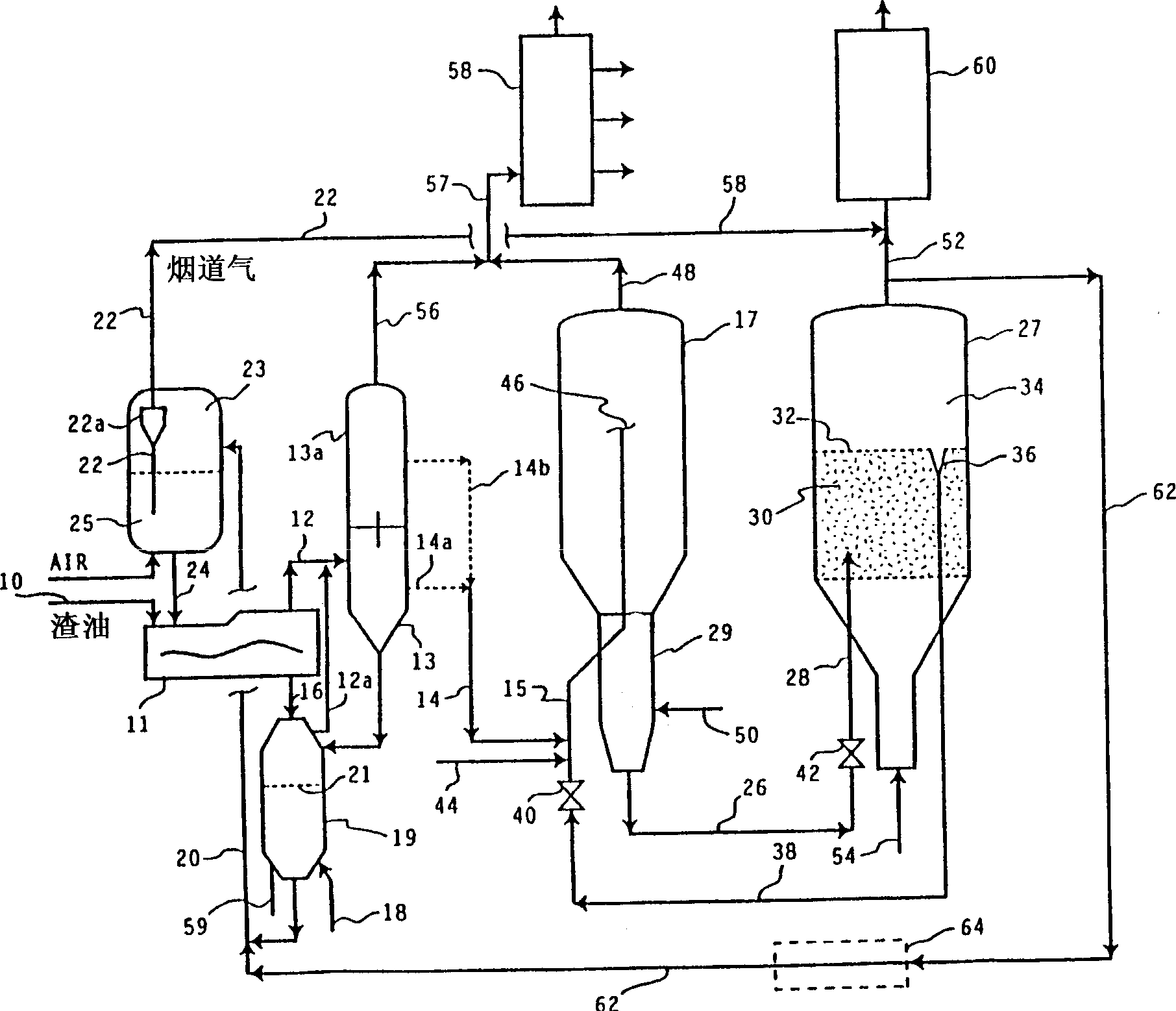
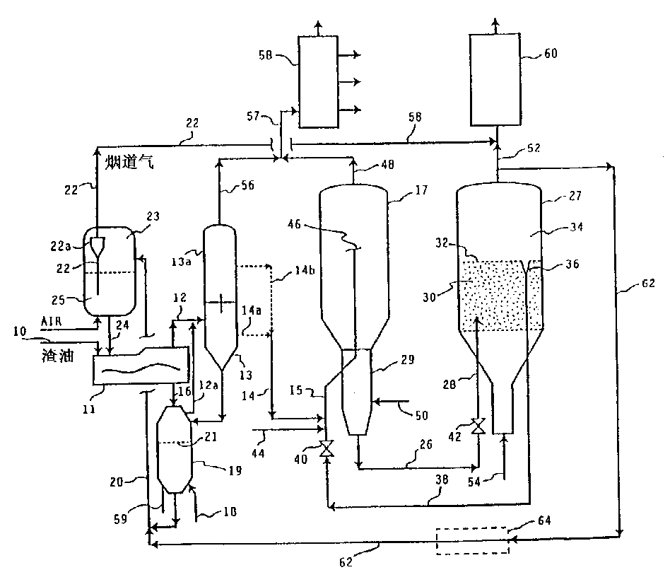
[0025] The resid feed to be upgraded according to the present invention is a petroleum fraction that is liquid under process conditions and has an average boiling point above about 480°C, preferably above about 540°C, more preferably above about 560°C. Non-limiting examples of such fractions include vacuum residues, atmospheric residues, heavy and reduced petroleum crudes, tar pitches, saphalts, bitumen, tar sands, shale Oil and coal liquefaction residue. Preferred are vacuum residues, atmospheric residues and heavy and reduced petroleum crudes. It will be appreciated that such residues may also contain minor amounts of lower boiling materials. These feeds cannot be fed to FCC units in large quantities because they generally have a high Conradson carbon content and contain undesired amounts of metal-containing components. Conradson carbon deposits on the FCC cracking catalyst and can cause excessive deactivation. Metals such as nickel and vanadium also act as catalyst poiso...


PUM

PropertyMeasurementUnit
boiling pointaaaaaaaaaa
particle sizeaaaaaaaaaa

Abstract

A residuum feedstock is upgraded in a short vapor contact time thermal process unit (11) comprised of a horizontal moving bed of fluidized hot particles and is then fed to a fluid catalytic cracking reactor (17). Hot flue gases from the fluid catalytic cracking regenerator (27) are used to circulate solid particles and to provide process heat to the thermal process unit (11).

Description

[0001] Statement on Application [0002] This application is a continuation-in-part of USSN 081503,291 filed July 17,1995. field of invention [0003] The present invention relates to a process in which a residual oil feed is upgraded in a short vapor phase contact time heat treatment unit consisting of a horizontally moving bed of hot fluidized particles before being sent to a fluid catalytic cracking treatment unit. The hot flue gas from the FCC unit is used to recycle the solids and to provide process heat to the thermal treatment unit. Background of the invention [0004] While refineries produce many products, the most desirable are the transportation fuels gasoline, diesel and jet fuel, and light fuel oils, all of which are relatively high-volume, high-value products. Although light fuel oil is not a transportation fuel, its hydrocarbon components are interchangeable with diesel and jet fuels, the main difference being their additives. Therefore, one of the main obje...

Claims


Application Information

Patent Timeline
Patent Type & Authority Applications(China)
IPC IPC(8): C10B55/10C10G9/32C10G25/09C10G31/06C10G51/04C10G55/02C10G55/06C10G57/00
CPCC10G55/06C10G57/00C10G25/09C10G51/04C10G9/32C10B55/10C10G31/06
Inventor W·瑟兰德D·G·哈蒙德M·加科伯森J·F·帕格尔M·C·普勒
Owner EXXON RES & ENG CO
Why Eureka
Try Eureka