Conductive material using carbon nano-tube, and manufacturing method thereof

A technology of conductive materials and carbon nanotubes, applied in the direction of conductive materials dispersed in non-conductive inorganic materials, cable/conductor manufacturing, hybrid/electric double layer capacitor manufacturing, etc., can solve high production costs, not suitable for mass production, etc. question

Inactive Publication Date: 2006-12-20
HITACHI ZOSEN CORP +1
View PDF4 Cites 0 Cited by
  • Summary
  • Abstract
  • Description
  • Claims
  • Application Information

AI Technical Summary

Problems solved by technology

[0010] However, this invention uses a chemical vapor deposition process (CVD process) in an atmosphere of at least 600° C. for making a carbon nanotube electrode, so the process requires the use of a substrate of metal, glass, or similar heat-resistant material, thus resulting in high Cost of production
Therefore, there is a problem that the treatment is not suitable for mass production

Method used


Image

  • Conductive material using carbon nano-tube, and manufacturing method thereof
  • Conductive material using carbon nano-tube, and manufacturing method thereof
  • Conductive material using carbon nano-tube, and manufacturing method thereof

Examples


example 1

[0038] [first step]

[0039] The Fe complex solution was sprayed onto a low-resistance N-type semiconductor silicon substrate with a thickness of 0.5 mm, and the substrate was heated to 220° C. for ion coating formation.

[0040] [Step 2]

[0041] The ion coating on the substrate is put into the CVD equipment. Acetylene as a raw material for carbon nanotubes was introduced into the CVD apparatus at a temperature of about 720° C. at a flow rate of 30 ml / min for 15 minutes. When heated in this way, the ion coating becomes fine particles, and with the obtained catalyst fine particles as nuclei, bristle-like carbon nanotubes are fabricated and gradually grown. The grown carbon nanotubes had a multilayer structure and were 12 nm thick and 50 μm long.

[0042] [third step]

[0043] The obtained bristle-like carbon nanotubes were pressed against a conductive film (CF48, product of Toray Industries Co., Ltd.) with a thickness of 0.2 mm at their outer ends, and heated to a temperat...

example 2

[0047] This example demonstrates a method for producing carbon nanotube electrodes by continuously performing the steps in Example 1.

[0048] [first step]

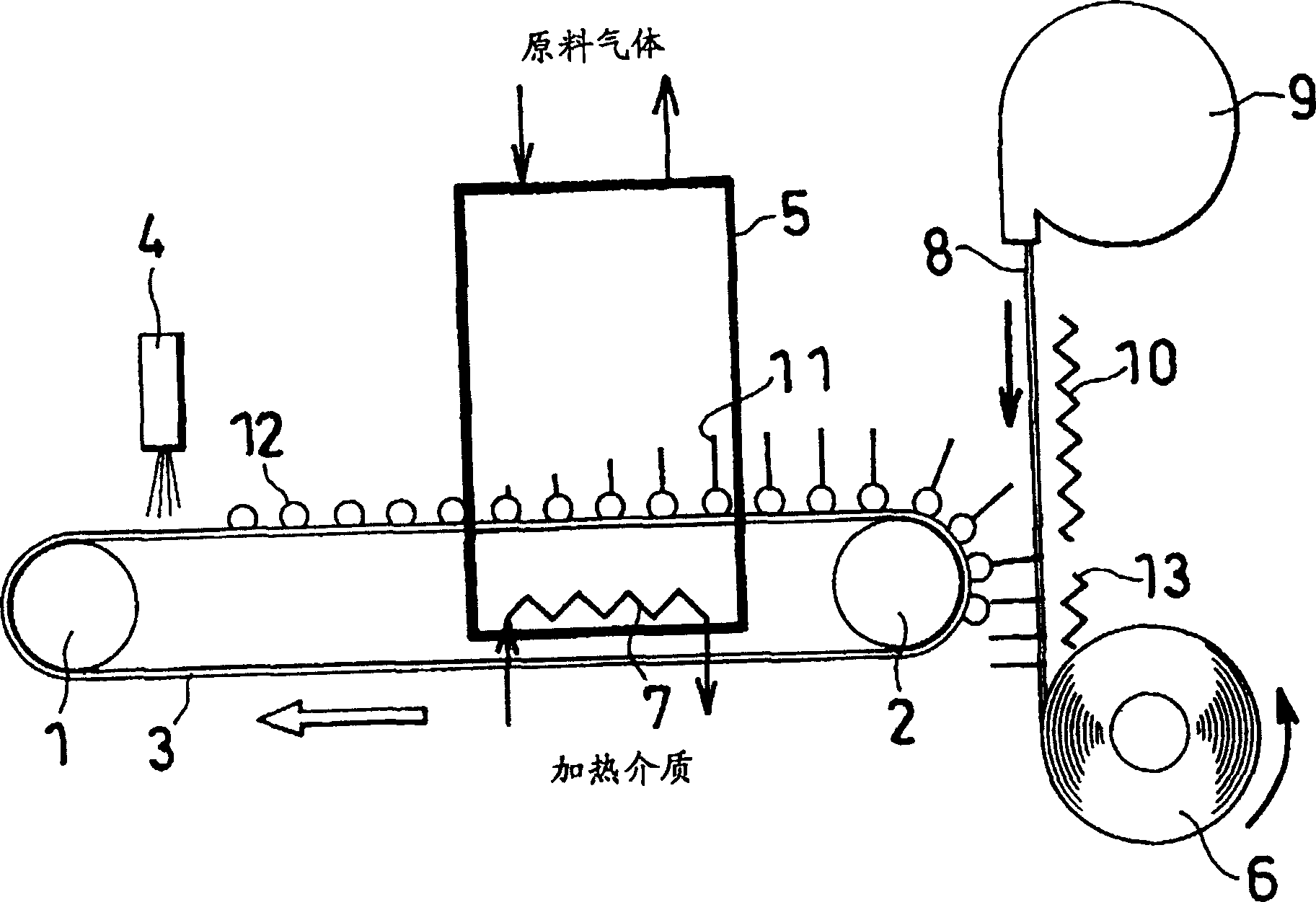
[0049] figure 1 An endless belt 3 (comprising a low-resistance N-type silicon substrate with a thickness of 0.5 mm) driven by the driving drum 1 and the driving drum 2 at a supply speed of 12 m / h is shown. The Fe complex solution is supplied from the injector 4 to the upper surface of the endless belt 3 in the catalyst deposition region of the upper side upstream portion of the belt 3, and then heated to 220° C., whereby the catalyst fine particles 12 are The stripes 3 are dispersedly formed at a pitch of 100 nm.

[0050] [Step 2]

[0051] The catalyst particles 12 on the endless belt 3 are transported to a CVD zone downstream of a catalyst deposition zone. The CVD zone comprises a furnace 5 having a length of about 2 m in the direction of belt movement and a heater 7 located inside the furnace 5 below the belt 3 . A...

example 3

[0057] [first step]

[0058] Execute the same procedure as in Example 1.

[0059] [Step 2]

[0060] Execute the same procedure as in Example 1.

[0061] [third step]

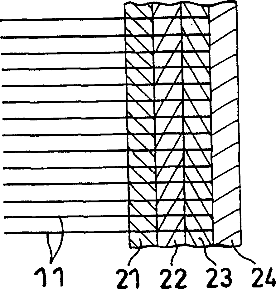
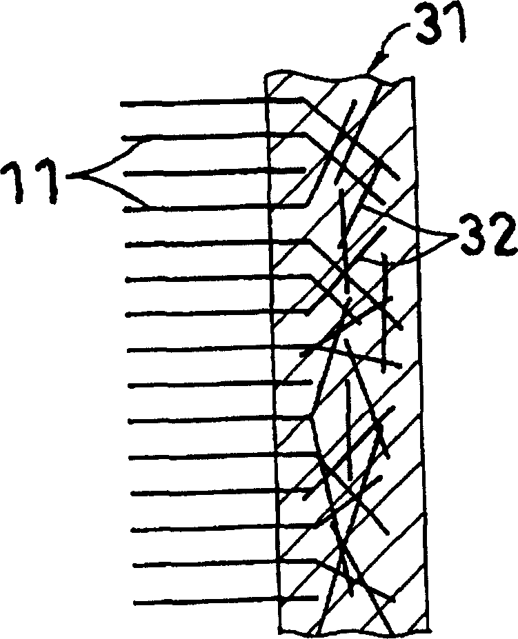
[0062] The bristle-shaped carbon nanotubes 11 formed in the second step on the 0.5mm thick low-resistance N-type semiconductor silicon substrate are pressed on their outer ends, and pressed against a multilayer conductive film heated at 95°C, thereby The carbon nanotubes are planted within the conductive film substantially perpendicular to the film surface. refer to figure 2 , arranged from the transfer side to the other side, the multilayer conductive film includes an ITO (indium tin oxide) layer 21 with a thickness of 0.01 to 0.03 μm, a base layer 22 with a thickness of 0.05 to 0.5 μm, and a thickness of 20 to 0.5 μm. A polyethylene layer 23 of 50 μm and a polyethylene terephthalate layer 24 having a thickness of 50 to 180 μm. The polyethylene layer may contain other thermally resistant films.

[0063]...


PUM

PropertyMeasurementUnit
diameteraaaaaaaaaa
thicknessaaaaaaaaaa
diameteraaaaaaaaaa

Abstract

A carbon nano-tube electrode suitable for mass production and favorable in the cost aspect. Its production method is also disclosed. When the carbon nano-tube of catalyst particles on an endless belt reaches from a chemical vapor deposition zone to a transfer zone by the movement of the belt, and is gradually collapsed horizontally as the tube is turned around the outer side of a driven drum, the carbon nano-tube is pressed against a conductive film from a tip thereof. The conductive film is fed downwardly from a film feeder, and heated by a heater to the temperature not lower than the softening point and not higher than the melting point. By pressing the carbon nano-tube against the conductive film, the carbon nano-tube is transferred to a surface of the conductive film from the catalyst particles in a substantially perpendicular manner.

Description

technical field [0001] The invention relates to a conductive material containing carbon nanotubes and a manufacturing method thereof. The conductive material of the present invention can be used, for example, for an electrode which is a main part of an electric double layer capacitor having a large storage capacity. The present invention also relates to a conductive material comprising carbon nanotubes, which resemble elongated brush bristles, and are useful when carbon nanotubes are used as fuel cell electrodes, environmental cleaning catalytic materials, electron sources, electrical High linearity and great value in materials, probe detectors and gas storage materials. Background technique [0002] A conventional electric double layer capacitor comprises a capacitive element comprising a pair of polarizable electrodes and a separator, each polarizable electrode is prepared by forming a polarizable electrode layer, mainly activated carbon, above a current collector, the se...

Claims


Application Information

Patent Timeline
Patent Type & Authority Patents(China)
IPC IPC(8): H01B13/00C01B31/02H01G9/058B82Y30/00B82Y99/00H01B1/04H01B1/24H01G9/00H01G11/22H01G11/36H01G11/86H01M4/96
CPCB82Y40/00H01B1/24C01B31/0233H01G11/36H01G9/058B82Y30/00H01M4/96Y02E60/50Y02E60/13H01G9/155C01B32/162H01B1/04H01B13/00
Inventor 中山喜万稻住近盐崎秀喜藤田大祐
Owner HITACHI ZOSEN CORP
Why Eureka
Try Eureka