

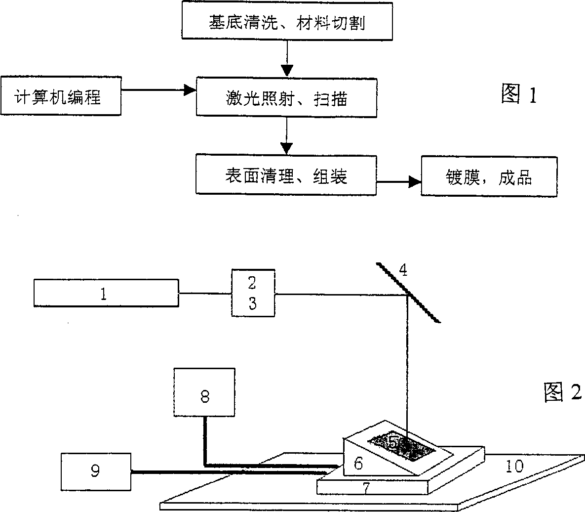
Holographic grating making process
A manufacturing method and technology of holographic gratings, applied in the field of integrated optics, can solve problems such as difficult control, high difficulty, and inapplicability, and achieve the effects of easy control, cost control, and convenient selection
- Summary
- Abstract
- Description
- Claims
- Application Information
AI Technical Summary
Problems solved by technology
Method used
Image

Examples
Embodiment 1
[0019] The grating material uses a polymer called polyimide. Use 3,3',4,4'-tetraacid dianhydride benzophenone and 3,3'-dimethyl-4,4'-diaminodiphenylmethane as diamine to prepare polyimide , dissolved in N-methyl-2-pyrrolidone to form a solution, and the solid content is controlled at about 10%. The solution was spin-coated on a cleaned glass plate, and the temperature was raised step by step to volatilize the solvent, and a polyimide film with a thickness of about 1 micron was obtained on the substrate.
[0020] Place the substrate on a laser scanning mobile platform, the moving direction of the platform is parallel to the laser polarization direction, adjust the laser pulse width to 5ns, the pulse frequency to 10Hz, the wavelength to 355nm, the incident angle to 20°, and the incident beam power density to 20mJ / cm 2 , the polarization direction is in-plane polarization, the moving speed is 0.5mm / s, and the number of repeated scans is 5 times. From the obtained atomic force m...
Embodiment 2
[0022] Prepare the polyimide film with the same method as in Example 1, the platform movement direction is perpendicular to the laser polarization direction, adjust the laser pulse width to be 5ns, the pulse frequency is 10Hz, the wavelength is 266nm, the incident angle is 20 °, and the incident beam power The density is 30mJ / cm 2 , the polarization direction is in-plane polarization, the moving speed is 0.005mm / s in the X direction, and 5mm / s in the Y direction. A very regular surface groove structure is also obtained.
Embodiment 3
[0024] The polymer is selected from polyethylene terephthalate (PET) film, and the thickness of the film is about 0.5mm. Fix the film on the mobile platform, the moving direction of the platform is parallel to the laser polarization direction, adjust the pulse width to 5ns, the pulse frequency to 10Hz, the wavelength to 248nm, the incident angle to 20°, and the incident beam power density to 5mJ / cm 2 , the polarization direction is in-plane polarization, the moving speed is 0.5mm / s, and the number of repeated scans is 7 times.
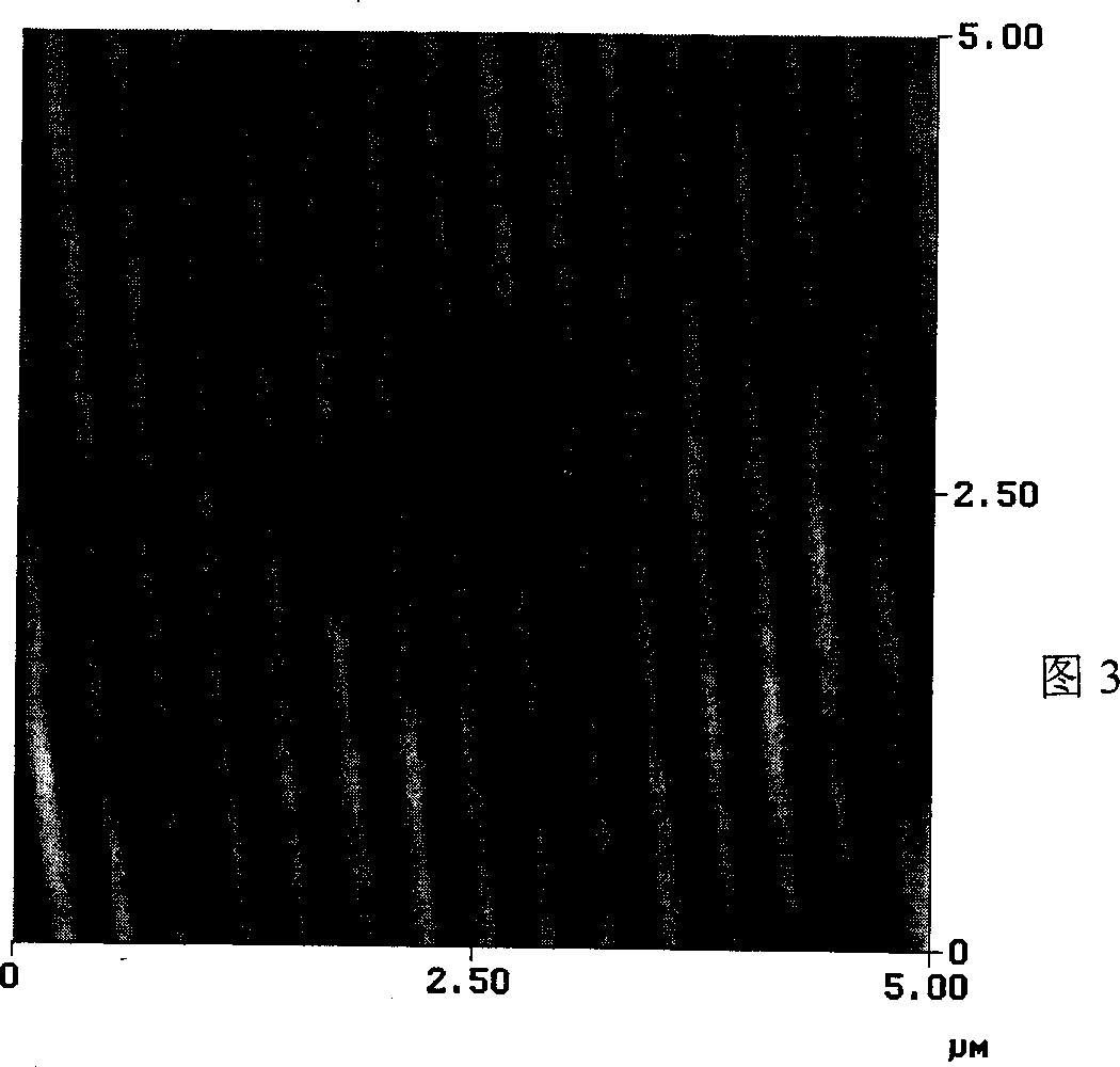
[0025] FIG. 3 is an atomic force microscope image of the trench structure obtained in Example 1. FIG.
[0026] As can be seen from the figure, the surface groove pitch obtained on the polyimide surface in Example 1 is about 330nm, and the measured depth is about 90nm;
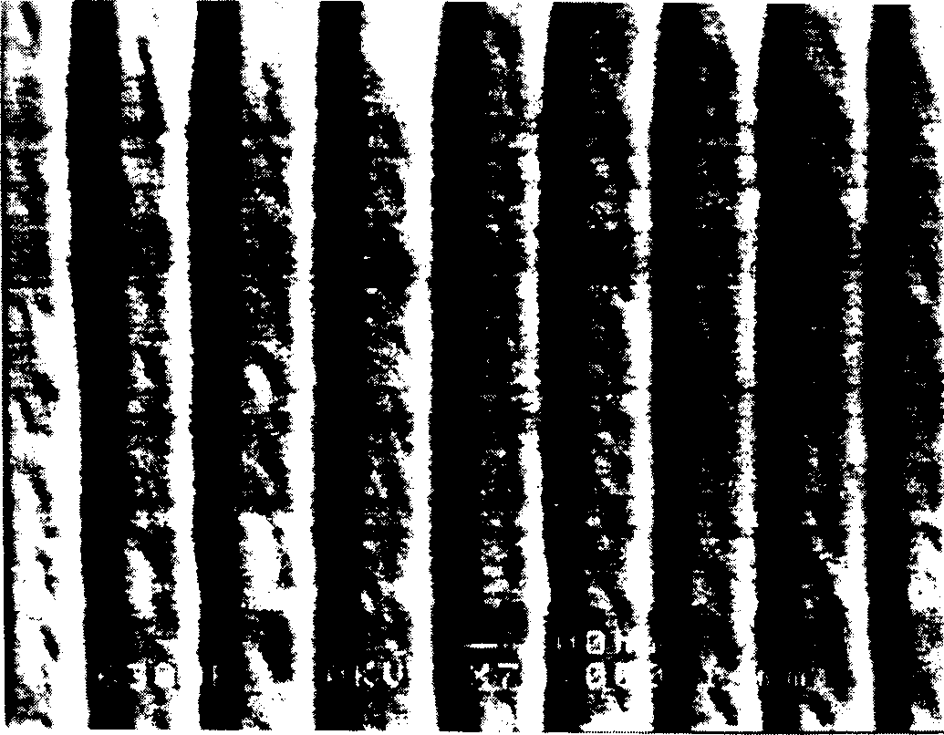
[0027] Figure 4 It is a scanning electron microscope image of the trench structure obtained in Example 2.
[0028] As can be seen from the figure, the surface groove pitch obtained o...
PUM
 Abstract
Description
Claims
Application Information