

Operation circuit and operation method
A computing circuit and computing method technology, applied in the field of computing circuits and computing, can solve problems such as memory access bottlenecks, and achieve the effect of low cost
- Summary
- Abstract
- Description
- Claims
- Application Information
AI Technical Summary
Problems solved by technology
Method used
Image

Examples
Embodiment 1
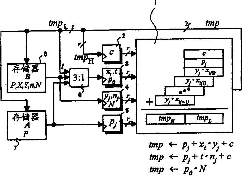
[0100] figure 1 is a block diagram representing the data path portion of an exemplary Montegomery multiplier suitable for use in the first embodiment of the present invention. The Montgomery multiplier in this embodiment comprises: a multiplier-adder 1, input registers 2 to 5, a multiplexer 6 and two memories 7 and 8 (memory A and memory B).
[0101] Multiplier Adder 1 adds the input values (r-bit length) of registers 2 and 5 to the product of the input values (r-bit length) of registers 3 and 4, and obtains an output tmp having a 2r-bit length. i.e. input p from addition j sum c and multiplication input y j and x i get output tmp=p j +y j x i +c. The multiplier-adder 1 can consist of, for example, a well-known full adder FA and a half adder HA. exist figure 1 in, such as x i(0) Such a value represents the value applied to the variable x obtained by extracting the bits corresponding to the numbers in parentheses i value.
[0102] Data is read from the memorie...
Embodiment 2
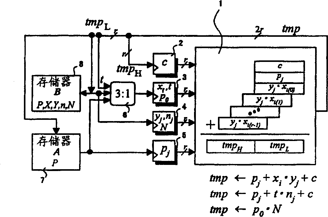
[0118] image 3 is a block diagram showing the data path portion of an exemplary Montegomery multiplier suitable for use in the second embodiment of the present invention. The arithmetic circuit in this embodiment is the same as in the first embodiment except that the memory 8 (memory B) is a single-port memory, ie the same port is used for both data reading and data writing. In this embodiment, since a one-port memory is used as the memory 8, the size of the memory is reduced so that a smaller circuit can be obtained.
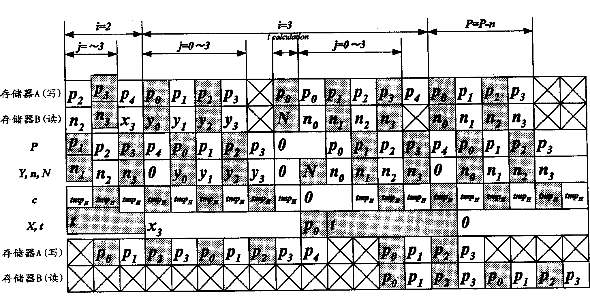
[0119] Figure 4 is represented by the example applicable to pseudocode 3.x, image 3 A timing diagram of the timing of the processing performed by the circuits in . exist Figure 4 In , the case near the final cycle is shown when m=4. Such as Figure 4 As shown in , until the i loop is terminated, the processing is the same as in the first embodiment. In the process of executing P=P-n, since a single-port memory is used as the memory 8 in this embodime...
Embodiment 3
[0121] Figure 5 is a block diagram showing the data path portion of an exemplary Montegomery multiplier suitable for use in the third embodiment of the present invention. The Montegomeri multiplier of this embodiment includes a multiplier adder 9, input registers 10 to 15 and three memories 16, 17 and 18 (memory A, memory B1 and memory B2).
[0122] Multiplier adder 9 increments the input value (r bit long register 11 (t register) and register 12 (n j , N register), register 13 (x i register) and register 14 (y j register) of the input value (r bit length), and the input value of register 10 (c register) (r+1 bit length), and register 15 (p j register) and provide as output tmp with a length of 2r+1 bits. That is, the multiplier-adder 9 has two multipliers, and from the corresponding p j , the addition input of c, corresponding to y j , x i The product of the input and corresponding to t, n j The product of the inputs obtains the output tmp = p j +y j x i +t·n j ....
PUM
 Abstract
Description
Claims
Application Information