High-energy accumlator with nano active carbone fibres (CNT) electrode

A nano-carbon fiber and battery technology, applied in the direction of active material electrodes, lead-acid batteries, lead-acid battery electrodes, etc., can solve the problems of reducing payload and effective energy consumption, and achieve shortened charging time, reduced weight, and high specific energy Effect

Inactive Publication Date: 2002-09-18
牛锡贤
View PDF0 Cites 10 Cited by
  • Summary
  • Abstract
  • Description
  • Claims
  • Application Information

AI Technical Summary

Problems solved by technology

This shortcoming greatly limits the further expansion of its application range, and greatly reduces the payload and effective energy consumption of moving tools and equipment such as automobiles, railway locomotives, passenger cars, airplanes, ships, and tanks.

Method used


Image

  • High-energy accumlator with nano active carbone fibres (CNT) electrode
  • High-energy accumlator with nano active carbone fibres (CNT) electrode
  • High-energy accumlator with nano active carbone fibres (CNT) electrode

Examples


Embodiment 1

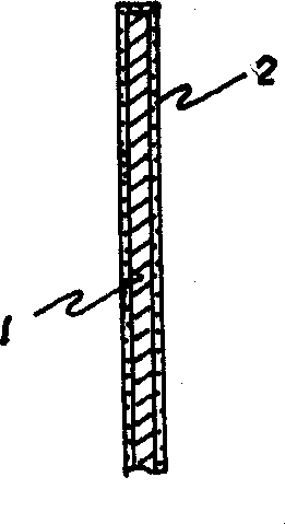
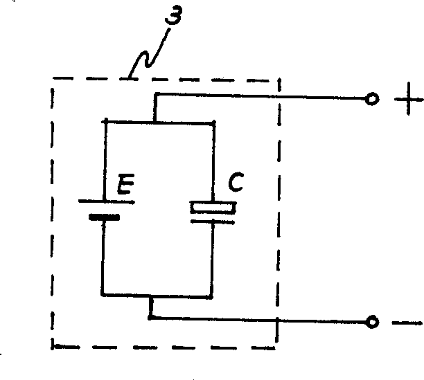
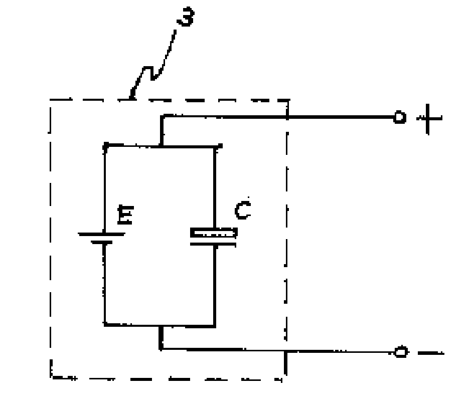
[0018] Embodiment 1. A kind of active carbon nanofiber (CNT) electrode high-energy accumulator. It consists of battery tank, tank cover, electrolyte, positive and negative plates, diaphragm and positive and negative electrodes. The positive plate is composed of an aluminum grid and an active nano-carbon fiber layer, and the negative plate is composed of a copper grid and an active nano-carbon fiber layer. The active carbon nanofibers have a diameter of 20nm and a length of 290nm. Each set of positive and negative plates and their separators have a small spacing that makes them large capacitors. It is equivalent to connecting this large capacitor in parallel with the battery. The diaphragm is made of polymer non-woven fabric with high dielectric strength, and its size is the same as the internal size of the battery tank. It can charge and discharge with high current, and the charging time is shortened to 1 / 17 of the past. The specific energy is as high as 8 times that of co...

Embodiment 2

[0019] Embodiment 2. An active carbon nanofiber (CNT) electrode high-energy storage battery, which belongs to storage battery technology. It consists of battery tank, tank cover, electrolyte, positive and negative plates, diaphragm and positive and negative electrodes. The positive plate is composed of an aluminum grid and an active nano-carbon fiber layer, and the negative plate is composed of a copper grid and an active nano-carbon fiber layer. The active carbon nanofibers have a diameter of 80nm and a length of 300nm. The rest are the same as embodiment 1. It can charge and discharge with high current, and the charging time is shortened to 1 / 10 of the past. The specific energy is up to 7 times that of conventional lead-acid batteries, and the weight is greatly reduced.

Embodiment 3

[0020] Embodiment 3. An active carbon nanofiber (CNT) electrode high-energy storage battery, which belongs to storage battery technology. It consists of battery tank, tank cover, electrolyte, positive and negative plates, diaphragm and positive and negative electrodes. The positive plate is composed of an aluminum grid and an active nano-carbon fiber layer, and the negative plate is composed of a copper grid and an active nano-carbon fiber layer. The active carbon nanofibers have a diameter of 60nm and a length of 200nm. The rest are the same as embodiment 1. It can charge and discharge with high current, and the charging time is shortened to 1 / 20 of the past. The specific energy is as high as 10 times that of conventional lead-acid batteries, and the weight is greatly reduced.

[0021] Embodiments 1 to 3 can be widely used in various fields such as industrial equipment, vehicles, and national defense weapons.


PUM

PropertyMeasurementUnit
diameteraaaaaaaaaa
lengthaaaaaaaaaa
diameteraaaaaaaaaa

Abstract

The invention relates to a high-energy accumulator of active nano carbon fiber belonging to technique of accumulator. It is composed of battery jar, capping, electrolyte, positive and negative polar plates, diaphragm and positve and negative electrodes. The positive polar plate consists of grating of aluminium plate and layer of active nano carbon fiber. The negative polar plate consists of grating of copper plate and layer of active nano carbon fiber. Diameter of the carbon fiber is 20-300nm. Spacing intervals of each group of positive, negative polar plates and diaphragm are small so as to provide large capacity. It is Equivalent to parallel connectino between the large capacity and accumulator. The diaphragm is prepared by use of macromolecular non-woven fabric with high dielectric strength.

Description

technical field [0001] The invention belongs to the technical field of electrochemical accumulators, and more specifically relates to a high-energy accumulator with activated carbon nanofiber (CNT) electrodes. Background technique [0002] Since Plante invented the lead-acid battery in 1860, people have mainly developed and researched in the electrochemical range, made uninterrupted efforts, and made continuous progress in technology. [0003] However, the existing accumulator still has many defects and deficiencies. One of them is that the charging time is too long, which seriously limits the practical application of the storage battery. In the past, because of the small specific surface area of ​​the plates, only chemical methods can be used for long-term charging, and high current charging and discharging cannot be used. Otherwise, when charging with a large current, the plate will easily generate Joule heat and be used to decompose water, re...

Claims


Application Information

Patent Timeline
Patent Type & Authority Applications(China)
IPC IPC(8): H01M2/16H01M4/14H01M4/583H01M10/04H01M10/12
CPCY02E60/10Y02P70/50
Inventor 牛锡贤
Owner 牛锡贤
Why Eureka
Try Eureka