Nano carbon tube composite high-energy accumualtor-separator gate

A carbon nanotube, battery technology, applied in the direction of electrode carrier/current collector, etc., can solve the problems of insufficient utilization of active materials, inability to meet high-rate charge and discharge, and reduced sulfate charging capacity, etc. The effect of current discharge performance, shortening of formation time, and improvement of surface activation

Inactive Publication Date: 2002-11-20
乌日根
View PDF0 Cites 8 Cited by
  • Summary
  • Abstract
  • Description
  • Claims
  • Application Information

AI Technical Summary

Problems solved by technology

This kind of grid pollutes the environment very seriously during the casting process, so the real surface area of ​​the electrode grid is often very small, and the utilization rate of active materials cannot be fully utilized, generally below 40%. Influenced by night and night factors, therefore, from the point of view of the weight-to-energy ratio of lead-acid batteries, the energy that can actually be achieved is very low, and it cannot meet the needs of high-rate charge and discharge, especially after over-discharge and shelving, it is easy to generate sulfuric acid with no electroactivity Salt reduces charging ability

Method used


Image

  • Nano carbon tube composite high-energy accumualtor-separator gate
  • Nano carbon tube composite high-energy accumualtor-separator gate

Examples


Embodiment

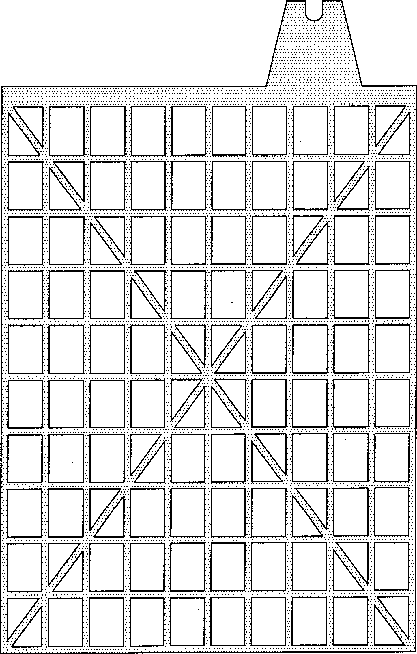
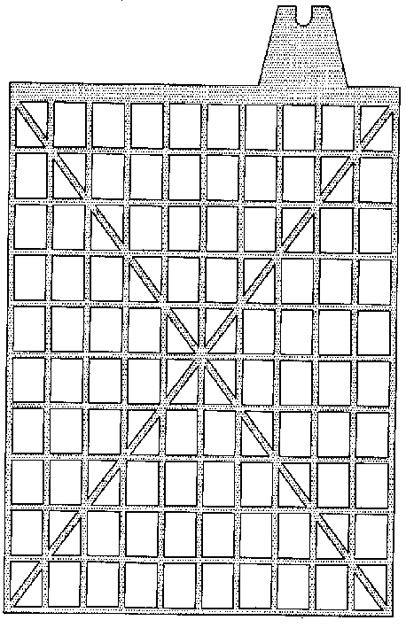
[0010] Embodiment (see figure):

[0011] Take 0.02% by weight of carbon nanotubes, 1.2% of carbon fibers, 1.7% of glass fibers and 97.08% of silicon nitride powder and mix them evenly, and put them together with 107 floor glue with a total weight of about 5%. After the mold is pressed and formed, put it into a constant temperature box and dry it to make the water content reach 0.1-0.5%, and sinter it in a sintering furnace for 1.5 hours at a temperature of 680°C-1700°C, then slowly cool down to close to room temperature and leave the furnace for grid skeleton sintering. ; The surface of the grid is coated with lead paste for 3 days, and after 20 to 25 hours of chemical formation, the battery can be assembled; the shape of the grid is rectangular, and the grid is rectangular. In order to increase its strength, there is an "X" on the grid Type ribs, one side of the grid is provided with a mounting handle.


PUM

PropertyMeasurementUnit
porosityaaaaaaaaaa

Abstract

The invention relates to the slab lattice of high-energy accumulator made of the composite nanometer carbon tube. The ingredient of the slab lattice includes nanometer carbon tube, carbon fiber and silicon nitride. With the said ingredient being mixed and with 107 floor glue being added and mixed evently, die stamping the said mixed material obtains the roughts. The agglutinated slab lattices areobtained by heat drying, agglutinating the roughs then cooling down the roughs slowly. Lead plaster in 3 days screen mesh is coated on the slab lattice. After 20-25 hours, the slab lattice can be used to assemble the accumulator.

Description

technical field [0001] A carbon nanotube composite high-energy storage battery grid, the invention relates to a storage battery grid of a novel composite material. Background technique [0002] For the basic structure of the lead-acid battery (lead), the old casting grid manufacturing method is still used at present, and the weight of this lead grid accounts for nearly 1 / 2 of the weight of the entire electrode plate. This kind of grid pollutes the environment very seriously during the casting process, so the real surface area of ​​the electrode grid is often very small, and the utilization rate of active materials cannot be fully utilized, generally below 40%. Influenced by night and night factors, therefore, from the point of view of the weight-to-energy ratio of lead-acid batteries, the energy that can actually be achieved is very low, and it cannot meet the needs of high-rate charge and discharge, especially after over-discharge and shelving, it is easy to generate sulfur...

Claims


Application Information

Patent Timeline
Patent Type & Authority Applications(China)
IPC IPC(8): H01M4/68H01M4/73
CPCY02E60/10
Inventor 乌日根
Owner 乌日根
Why Eureka
Try Eureka