
Methane synthesizing method and equipment with slurry bed member

A methanol synthesis, slurry bed technology, applied in chemical instruments and methods, preparation of hydroxyl compounds, preparation of organic compounds, etc., can solve the problems of reduced catalyst utilization, incomplete reaction, shortened residence time, etc., to achieve yield Improved, easy temperature adjustment, the effect of great flexibility in operation

Inactive Publication Date: 2003-01-08
TSINGHUA UNIV
View PDF3 Cites 8 Cited by
  • Summary
  • Abstract
  • Description
  • Claims
  • Application Information

AI Technical Summary

Problems solved by technology

Such as Japanese Patent JP10080634~A2 and U.S. Patent US32040.6 etc. disclose slurry bed methanol synthesis technology; my country East China University of Science and Technology has developed a kind of three-phase bubbling slurry bed methanol synthesis process and device (applied by Zhu Bingchen, Ding Baiquan, Sun Songliang Chinese patent CN00115360.9), realize good dispersion and mixing effect in above-mentioned patented technology, improve mass transfer efficiency, need higher space velocity to promote its internal immersion, but will make reactant stay in the reactor like this The shorter the time, the lower the utilization rate of the catalyst and the incomplete reaction, thus reducing the conversion rate
Although the mechanical stirring tank can achieve a good effect of wetting, but due to its own limitations, it is currently mainly used in laboratory research, and there is still a long way to go for industrial production.

Method used


Image

  • Methane synthesizing method and equipment with slurry bed member
  • Methane synthesizing method and equipment with slurry bed member
  • Methane synthesizing method and equipment with slurry bed member

Examples


Embodiment 1

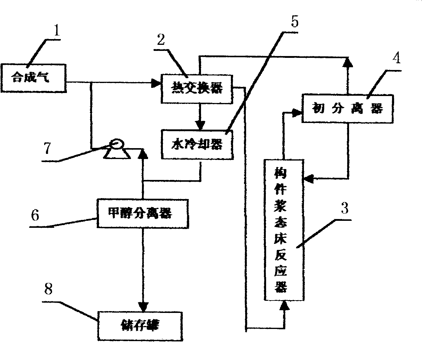
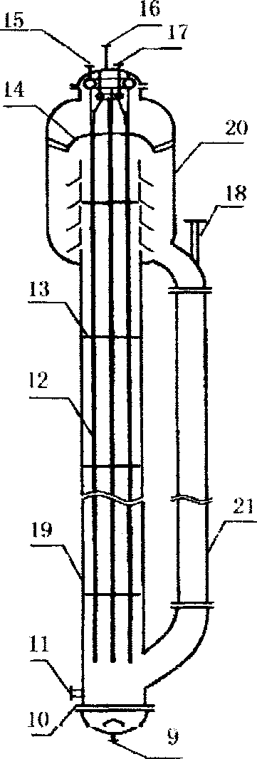
[0024] figure 1 Shown is the reaction process flow chart of methanol slurry bed synthesis. First from the catalyst slurry inlet 18 of the component slurry bed reactor 3 (such as figure 2 shown), add an inert solvent, liquid paraffin, and a methanol synthesis catalyst with a particle size of 150 to 180 meshes, the weight ratio of the catalyst to the inert solvent is 20%, and the methanol synthesis catalyst and the solvent form a slurry system together. Syngas (H 2 , CO, CO 2 )1 After reduction at a certain temperature and pressure, press H 2 / (CO+CO 2 ) is 2:1 synthesis, after heat exchange by the compressor pump 7 and the heat exchanger 2, the synthesis gas inlet 9 at the bottom of the reactor 3 is bubbled into the tank body 19 of the reactor 3 for reaction. Its reaction process is:

[0025] 1). Put H 2 / (CO+CO 2 ) the synthesis gas 1 with a volume ratio of 1:1 to 4:1, passes through the synthesis gas compression pump 7 and the heat exchanger 2, so that the synthesis ...

Embodiment 2

[0032] image 3 Shown is the progress of the methanol synthesis process in the component circulating slurry bed reactor, which is basically the same as in Example 1, the difference is that the weight ratio of the catalyst to the inert solvent is 30%, and the synthesis gas space velocity is 3000h -1 . The main products produced by the reaction are methanol and a small amount of methane, the single-pass conversion rate of CO can reach 55%, and the selectivity of methanol is greater than 98%. In addition, a gas-liquid separation chamber 20 is installed on the top of the reactor 3, and is communicated with the lower part of the tank body 19 by a downcomer 21.


PUM


Abstract

The present invention discloses a method for synthesizing methyl alcohol by using component slurry bed and its equiopment. Said invention utilizes the introduction of specific inert solvent, and makes it and fine granule catalyst and synthetic gas in the reactor form three-phase slurry bed reaction system; and adds internal component and gas distributor in the slurry bed reactor to make bubbles uniformly distribute in the reactor; its operation temp. is easily controlled, and service life of said catalyst is long, under the condition of low operatino gas speed the phase circulation can be increased, the mass transfer heat-transfer can be forcedly intensified, so that the interphase mass transfer speed in the slurry bed reactor can be greatly raised, and its reaction conversion rate can be raised.

Description

technical field [0001] The invention belongs to the technical category of alcohol synthesis, and in particular relates to a component slurry bed methanol synthesis method and equipment which are easy to control and have high production efficiency. technical background [0002] At present, the synthesis of methanol in industry is mainly carried out in fixed-bed gas-solid catalytic synthesis reactors, which have disadvantages such as single-pass conversion rate of synthesis gas and low concentration of methanol at the outlet of the synthesis tower. In recent years, a new three-phase bed methanol synthesis process has been developed, which has good heat transfer and stability, and the reaction temperature is easy to control. The single-pass conversion rate of carbon monoxide and carbon dioxide and the methanol content in the gas phase product are higher than those of the gas-solid phase catalytic method. In the application process of three-phase slurry bed, three-phase slurry b...

Claims


Application Information

Patent Timeline
IPC IPC(8): C07C29/151C07C29/152C07C31/04
Inventor 王金福黎汉生韩明汉王德峥金涌
Owner TSINGHUA UNIV
Learn More