Optical system with laser beam uniform irradiation

An optical system, a technology for uniform illumination, applied in the field of optical systems, can solve the problems of reduced degrees of freedom of the optical system, complex and complicated configuration of multiple mirrors, etc., and achieve the effect of uniform illumination intensity distribution

Inactive Publication Date: 2003-10-15
MITSUBISHI ELECTRIC CORP
View PDF4 Cites 20 Cited by
  • Summary
  • Abstract
  • Description
  • Claims
  • Application Information

AI Technical Summary

Problems solved by technology

Therefore, the arrangement of the plurality of mirrors becomes complicated, and there is a problem that the degree of freedom of the optical system that should be arranged as a heat treatment device is reduced.
In particular, when the o

Method used


Image

  • Optical system with laser beam uniform irradiation
  • Optical system with laser beam uniform irradiation
  • Optical system with laser beam uniform irradiation

Examples


Embodiment 1

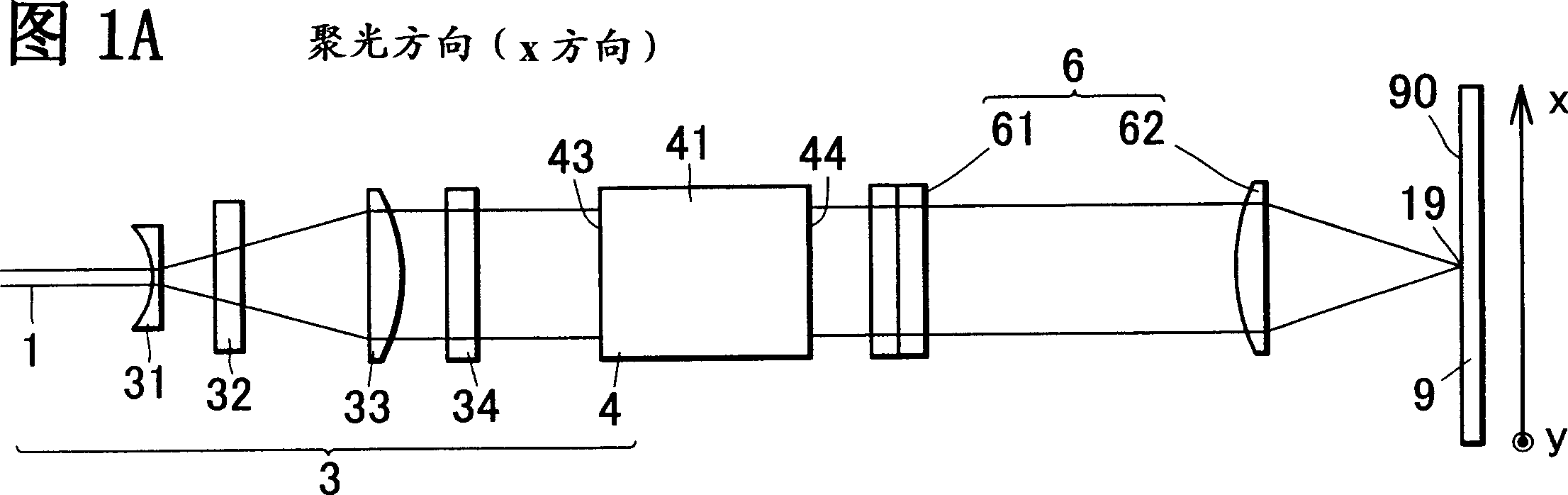
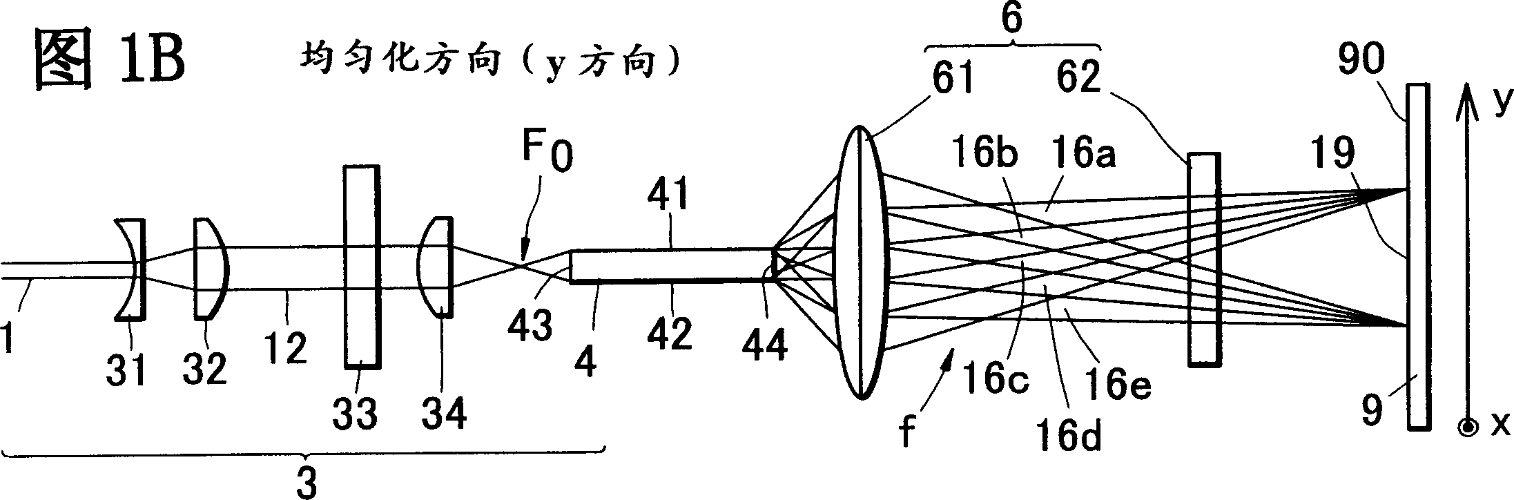
[0088] In Embodiment 1 of the present invention, Fig. 1A and Fig. 1B represent the optical system uniformly irradiated by the laser beam, but represent that the optical system is formed on the irradiated surface, spreads with a uniform distribution in the y direction, and converges into a line in the x direction An example of a straight-line irradiation profile.

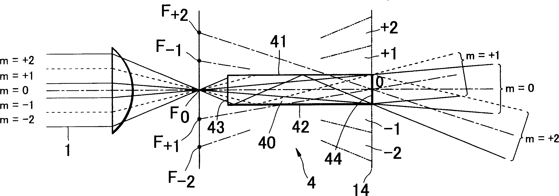
[0089] The optical system includes laser beam splitting means 3 and coincident irradiation means 6 (61, 62). In this example, the waveguide 4 is used in the laser beam splitting part 3 to split the laser beam 1 into a required number of split beams 16a-16e, and these split beams are imaged in a linear shape on the irradiation surface 90 by overlapping the irradiation part 6. Contoured illumination beam 19 .

[0090] In this embodiment, the laser beam splitting unit 3 includes an optical system for making the laser beam 1 from the laser oscillator incident into the waveguide 4, and includes a beam expander lens 31 an...

Embodiment 2

[0105] In this embodiment, a cylindrical lens array is used as another beam splitting component. As shown in FIGS. 8A and 8B in this example, the optical system for uniform irradiation of the laser beam includes an optical system for making the laser beam 1 from the laser oscillator incident to the cylindrical lens array 5, including a beam expander lens 31 for generating parallel beams. , a y-direction collimator lens 32 and an x-direction collimator lens 33 , the parallel beams from the collimator lens 33 are incident on the cylindrical lens array 5 .

[0106] In the cylindrical lens array 5, the cylindrical lens refers to a lens that is cylindrical in the x direction in the figure, and the cross-sectional convex lens is stacked in the y direction toward the optical axis, but the illustration includes five tiny cylindrical lenses 5a to 5e. Constituting, accordingly, five segmented bundles are formed.

[0107] Split beams 15 a to 15 e in the y direction from the cylindrical ...

Embodiment 3

[0112] In the optical system according to the embodiment of the present invention, the homogenizing means includes: one of the adjacent split beams formed by the waveguide is delayed by a time-interference distance of the laser beams with respect to the other. Long optical delay components. In order to prevent interference between the two split beams emitted from adjacent areas of the laser beam, the optical delay member provides an optical path difference equal to or greater than the time interference distance between the two split beams in the adjacent areas.

[0113] This example shows an optical system using a light-transmitting retardation plate as an optical retardation member. As shown in Fig. 12A and Fig. 12B, the optical system uses: the laser beam splitting part 3 utilizing the waveguide 4, the orthogonal two cylindrical lenses (61, 62) as the coincident irradiation part 6, the retardation part as the optical delay part plate 7. In this example, the waveguide 4 div...


PUM


Abstract

An optical system with laser beam uniform irradiation, comprises: a wave-guide space-dividing a laser beam from a light source into divided beams; a superposition lens by which the divided beams are superposition-irradiated on an irradiation face; a delay plate by which beam intensity on the irradiation face is uniform. The wave-guide makes width of the divided beams more than 1/2 times large of a space interference distance on a laser beam section; the delay plate makes a delay of the adjacent divided beams longer than an interference distance of the time of the laser beam, and reduces interference on the irradiation face. An other optical system comprises: a laser beam dividing component for dividing the laser beam into divided beams; a superposition-irradiation component for superposition-irradiating the divided beams on the irradiation face; a homogenization component for homogenizing beam intensity on the irradiation face. The homogenization component includes an optical delay component which makes a delay of the adjacent divided beams longer than an interference distance of the time of the laser beam, a light rotation component which makes polarization directions of the adjacent divided beams actual orthogonal.

Description

technical field [0001] The present invention relates to an optical system for uniform irradiation of a laser beam which improves the uniformity of the intensity distribution of an irradiation laser beam (laser beam) on an irradiation surface during laser treatment of an object to be irradiated. Background technique [0002] As an example of heat treatment using laser irradiation, it is known that, when a polysilicon film is produced, it is known in advance on a suitable substrate (such as a glass substrate) by a vapor deposition (vapor deposition) method such as chemical vapor deposition (CVD) A method in which an amorphous silicon film is formed and polycrystallized by scanning the amorphous silicon film with a laser beam. For example, U.S. Patent No. 5,529,951 discloses that in the assembly of semiconductor integrated circuits, amorphous silicon is formed on the polysilicon layer by evaporating amorphous silicon on the circuit components and irradiating excimer (excimer) l...

Claims


Application Information

Patent Timeline
IPC IPC(8): G02B27/10G02B27/28H01L21/324H01S3/00
CPCG02B3/08G02B27/0927H01S3/0071H01S5/0283
Inventor 岡本達樹森川和敏佐藤行雄西前順一小川哲也
Owner MITSUBISHI ELECTRIC CORP
Why Eureka
Try Eureka