Polarization mould disporsion compensation system

A polarization mode dispersion and compensation system technology, applied in transmission systems, polarization components, electromagnetic wave transmission systems, etc., can solve the problems of limited response speed, high driving voltage, high price, etc., and achieve easy dynamic control, stable performance, and simple structure. Effect

Inactive Publication Date: 2004-02-18
TSINGHUA UNIV
View PDF0 Cites 5 Cited by
  • Summary
  • Abstract
  • Description
  • Claims
  • Application Information

AI Technical Summary

Problems solved by technology

However, as proposed in patent WO01 / 61385, 2001 / 8 / 21, the method of using a polarization beam splitter and a common self-focusing lens as a polarization controller and a collimator has too many optical and mechanical components, which is not conducive to system integration.
In literature (4) S. Lee, etal, "Adjustable compensation of polarization mode dispersion using a high-birefringence nonlinearly chirped fiber Bragg grating", IEEE Photon.Technol.Lett., Vol.11, No.10, ppl277~1279, Oct. The method of using high birefringence nonlinear chirped fiber grating proposed in 1999, the production process is complex and expensive
Document (5) D.Sandel, etal, "10-Gb / s PMD compensation using deformed-helical ferroelectric liquid crystals", in Proc.ECOC'98 (Madrid), pp555~556 and patent US 6,417,948 B1, 2002 / 7 / 9 , put forward the "method of using liquid crystal as a polarization controller", but its reaction speed is limited due to the inherent properties of liquid crystal
Patent US 2002 / 0118455A1, 2002 / 8 / 29 "Compensation method using high birefringence material with equal length", when there is no PMD in the optical fiber, a certain amount of additional PMD is generated through the PMD compensator, while WO 01 In / 10811 A2, 2002 / 2 / 7, although the state of PMD is zero by adding electric birefringent crystal or liquid crystal, usually the driving voltage is high or the environmental requirements are high

Method used


Image

  • Polarization mould disporsion compensation system
  • Polarization mould disporsion compensation system

Examples


Embodiment Construction

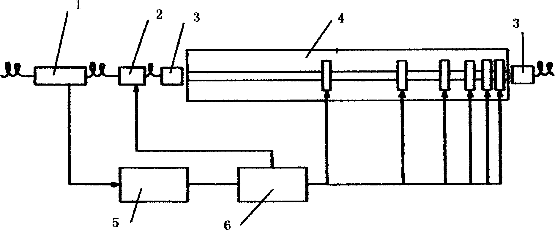
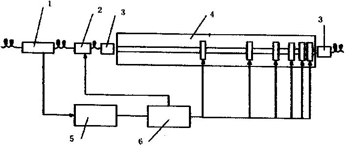
[0011] The invention provides a polarization mode dispersion compensation system which is easy to be coupled with the system, has quick response, low power consumption, is easy to implement in engineering and can be dynamically controlled. The optical collimator 3 of the system and the variable optical delay line 4 composed of n+1 birefringent crystals and n polarization rotators (PR) based on the magneto-optical effect are placed concentrically on a straight line with the optical axis (n is a certain natural number determined according to the maximum DGD value compensated by the optical fiber communication system and the allowed residual DGD value of the system). The above-mentioned crystals and PRs are spaced in such a way that from front to back they are the longest crystal, PR, the second longest crystal, PR, and finally the shortest crystal. The feedback control circuit includes a detector 5 and a computer 6 connected in series with the coupler 1, and the computer is conn...


PUM


Abstract

The system includes placing optical collimator and variable optical retardation line on a straight line, serial-connecting coupler, detector and computer and then forming feedback control circuit by connecting the computer separately with polarization controller and the said redaration line of which coupler, polarization controller and optical collimator having tail fibre device, polarization controller is controlled by DC servo motor and the said redardation line applies birefringer crystal and PR arranged in special manner. The directional information of system PMD is fed back by feedback control circuit to polarization controller circuit to generate counter-polarization state for counterbalancing to each other to realize purpose of polarization mode dispersion compensation.

Description

technical field [0001] The invention belongs to the field of optical fiber communication, in particular to a polarization mode dispersion compensation system. Background technique [0002] Polarization mode dispersion is an important cause of signal broadening in high-speed and large-capacity optical fiber communication systems. In an ideal optical fiber transmission system, the optical fiber has a circular symmetric structure. However, in the actual system, the optical fiber is not an ideal circular symmetric structure due to manufacturing reasons and the influence of temperature, vibration, stress, etc., which causes random birefringence. When a beam of optical signal is transmitted in such an optical fiber, the optical signal will be split, thereby causing pulse broadening. This phenomenon of pulse broadening is called polarization mode dispersion (PMD for short). When analyzing the PMD in the transmission system, the optical fiber is usually considered as a birefringen...

Claims


Application Information

Patent Timeline
Patent Type & Authority Applications(China)
IPC IPC(8): G02B5/30H04B10/2569
Inventor 杨昌喜李世光
Owner TSINGHUA UNIV
Why Eureka
Try Eureka