

Technology for producing wear-resisting compound material
A production process and composite material technology, applied in the field of metallurgy, to achieve the effect of stable production process and compact structure of alloy layer
- Summary
- Abstract
- Description
- Claims
- Application Information
AI Technical Summary
Problems solved by technology
Method used
Image

Examples
Embodiment 1
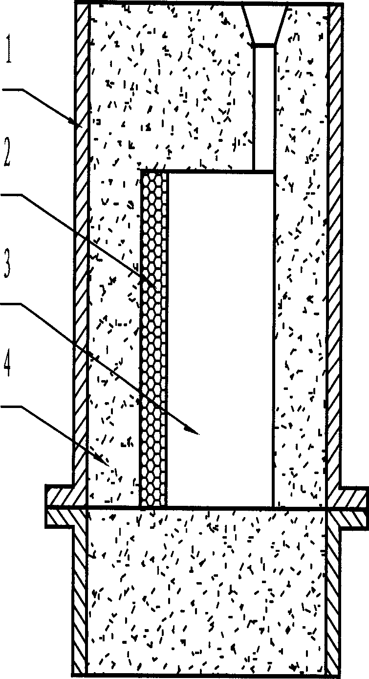
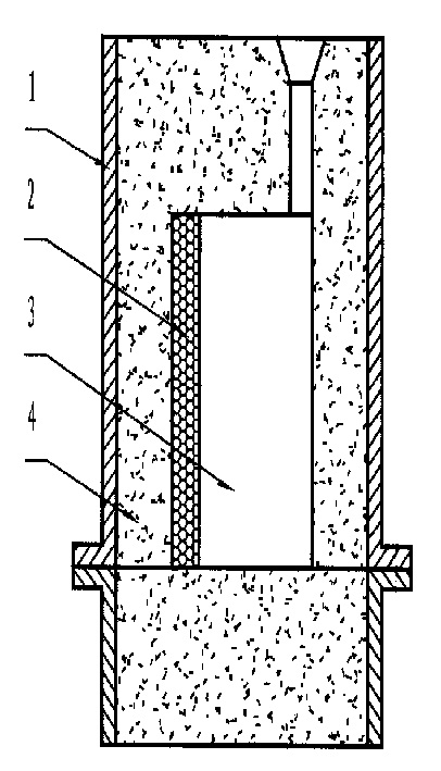
[0025] Such as figure 1 As shown in the figure, 1-flask, 2-alloy powder coating or alloy prefabricated body, can be in various shapes according to the requirements of the workpiece, which can be the inner or outer surface of the workpiece, 3-cavity, 4-casting mold.
[0026] The first step: selection and production of alloy layer materials: use alloy powder with a particle size of 0.005-0.8mm. The composition of alloy powder is: chromium (Cr), molybdenum (Mo), tungsten (W), vanadium (V), Titanium (Ti), nickel (Ni), cobalt (Co), manganese (Mn), boron (B), carbon (C), the binder is polyvinyl butyral alcohol solution, the binder and alloy powder Stir well and evenly to make alloy powder coating.
[0027] Step 2: Molding: Use water glass sand to mold. When molding, first create the cavity 3 of the required casting in the sand box 1, and set the wear-resistant working surface of the casting on the side of the mold 4. After the mold is solidified The alloy powder paint is coated on...
Embodiment 2
[0031] The first step: the selection and production of the alloy layer material: the alloy powder adopts the weight percentage of: 80% sintered hard alloy particles with a particle size of 0.4-0.8mm, 20% nickel (Ni) and chromium (Ni) with a particle size of 0.05-0.1mm Cr) powder, sintered cemented carbide is YG8 (its composition is tungsten carbide WC92%, cobalt Co8%), YG15 (its composition is tungsten carbide WC85%, cobalt Co15%) or YT14 (its composition is tungsten carbide WC78%, carbide Titanium TiC14%, cobalt Co8%). The binder is polyvinyl alcohol alcohol solution, and the binder and the alloy powder are fully stirred evenly to make the alloy powder coating.
[0032] Step 2: Molding: Use water glass sand to mold. When molding, first create the cavity 3 of the required casting in the sand box 1, and set the wear-resistant working surface of the casting on the side of the mold 4. After the mold is solidified The alloy powder paint is coated on the side of the mold 4 to form...
Embodiment 3
[0036] The first step: the selection and production of the alloy layer material: the alloy powder adopts the weight percentage of: 40% sintered hard alloy particles with a particle size of 0.4-0.8mm, 60% nickel (Ni) and chromium (Ni) with a particle size of 0.05-0.1mm Cr) powder, sintered cemented carbide is YG8 (its composition is tungsten carbide WC92%, cobalt Co8%), YG15 (its composition is tungsten carbide WC85%, cobalt Co15%) or YT14 (its composition is tungsten carbide WC78%, carbide Titanium TiC14%, cobalt Co8%). The binder is made of water glass, and the binder and the alloy powder are fully stirred evenly to make the alloy powder coating.
[0037]Step 2: Molding: resin sand molding is used. When molding, the cavity 3 of the required casting is first made in the sand box 1, and the wear-resistant working surface of the casting is set on the side of the mold 4. After the mold is solidified, the The alloy powder coating is coated on the side of the mold 4 to form the al...
PUM
| Property | Measurement | Unit |
|---|---|---|
| Granularity | aaaaa | aaaaa |
| Granularity | aaaaa | aaaaa |
| Granularity | aaaaa | aaaaa |
Abstract
Description
Claims
Application Information