

Method and reactor for removing nitrate in water
A technology for nitrate and water removal, applied in the direction of neutralized water/sewage treatment, reduced water/sewage treatment, etc., can solve the problems of poor impact load resistance, need for backflow, slow biological treatment, etc., and meet low requirements for operation management , fast reaction speed, fast denitrification effect
- Summary
- Abstract
- Description
- Claims
- Application Information
AI Technical Summary
Problems solved by technology
Method used
Image

Examples
Embodiment 1
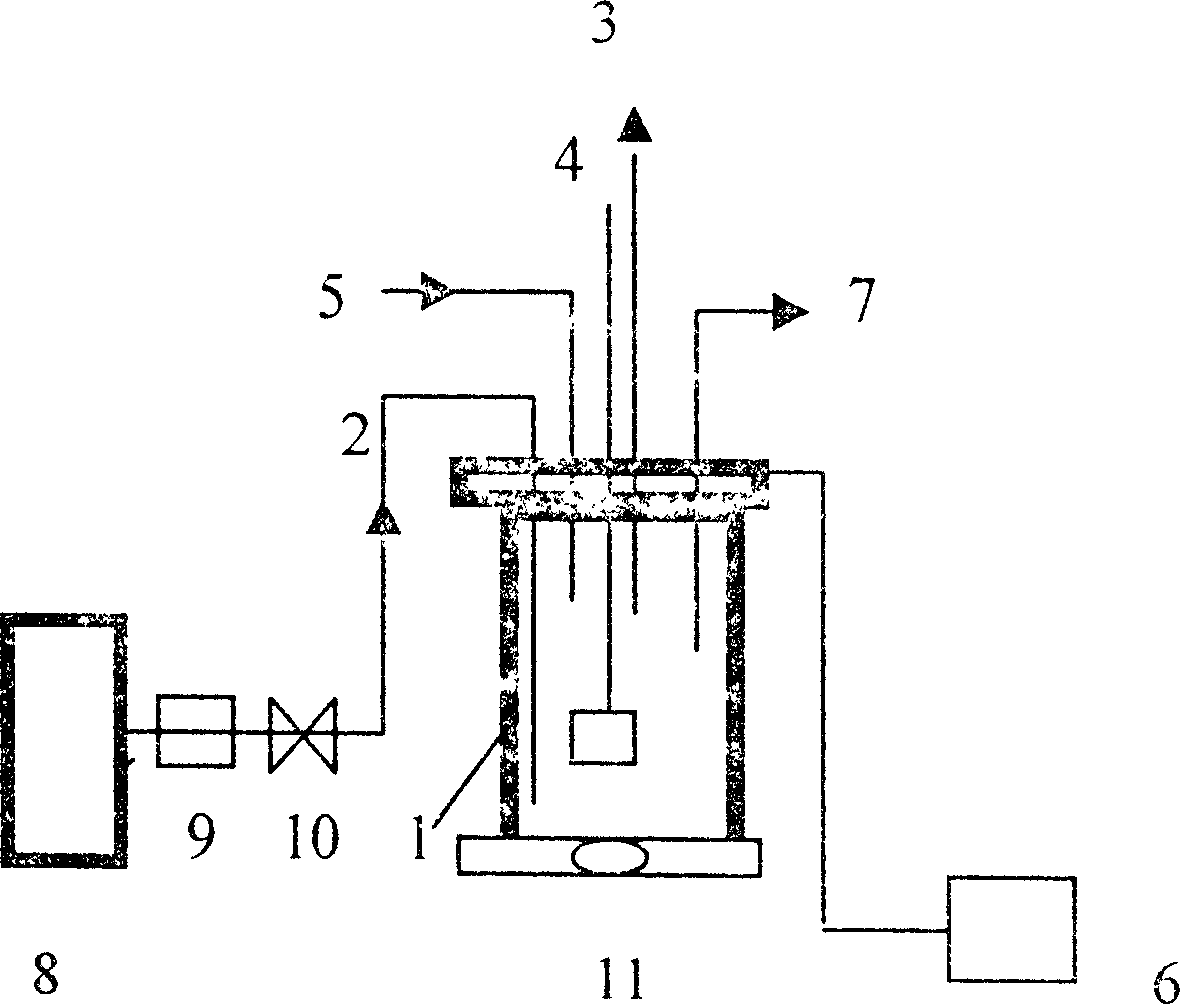
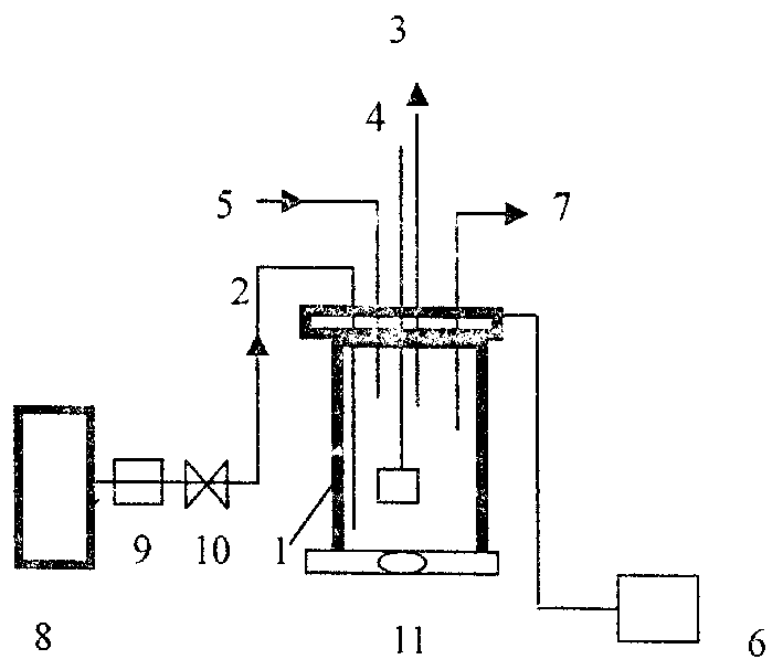
[0029] Example 1, add 900ml of distilled water and 2gPd-Cu / γ-Al in a closed stainless steel container with a volume of 1.5L 2 o 3 Catalyst, stir continuously at 300r / min with a magnetic stirrer, and continuously pass H in the container 2 After half an hour, add 1000mg / L NaNO 3 Solution 100ml, so that the total volume of the solution is 1000ml, the initial NaNO 3 The concentration is 100mg / L, and the reaction starts timing. The reaction temperature is 8 °C, H 2 The pressure and flow of the hydrogen generator are adjusted and controlled by the regulator and control valve at the outlet of the hydrogen generator. The pressure in the reactor was atmospheric pressure, and 0.5M HCl was used to adjust the pH to keep it at 5.2±0.2 during the reaction. When the reaction was carried out for 60 minutes, both the nitrate concentration and the nitrite concentration were less than 0.01 mg / L.
Embodiment 2
[0030] Embodiment 2, add the distilled water of 920ml and 1gPd-Cu / γ-Al in the closed stainless steel container that volume is 1.5L 2 o 3 Catalyst, stir continuously at 300r / min with a magnetic stirrer, and continuously pass H in the container 2 After half an hour, add 1000mg / L NaNO 3 solution 80ml, so that the total volume of the solution is 1000ml, the initial NaNO 3 The concentration is 80mg / L, and the reaction starts timing. The reaction temperature is 20 °C, H 2 The pressure and flow of the hydrogen generator are adjusted and controlled by the regulator and control valve at the outlet of the hydrogen generator. The pressure in the reactor was atmospheric pressure, and 0.2M HCl was used to adjust the pH to keep it at 4.0±0.2 during the reaction. When the reaction was carried out for 60 minutes, both the nitrate concentration and the nitrite concentration were less than 0.01 mg / L.
Embodiment 3
[0031] Embodiment 3, add the distilled water of 900ml and 1gPd-Cu / γ-Al in the closed stainless steel container that volume is 1.5L 2 o 3 Catalyst, stir continuously at 300r / min with a magnetic stirrer, and continuously pass H in the container 2 After half an hour, add 1000mg / L NaNO 3Solution 100ml, so that the total volume of the solution is 1000ml, the initial NaNO 3 The concentration is 100mg / L, and the reaction starts timing. The reaction temperature is 10 °C, H 2 The pressure and flow of the hydrogen generator are adjusted and controlled by the regulator and control valve at the outlet of the hydrogen generator. The pressure in the reactor is atmospheric pressure, and 0.1MH is used in the reaction process 2 SO 4 To adjust the pH to keep it at 6.0±0.2. When the reaction was carried out for 60 minutes, the nitrate concentration was 0.5 mg / L, and the nitrite concentration was <0.01 mg / L.
PUM
 Abstract
Description
Claims
Application Information