

Dielectric ceramic, method for making the same, and monolithic ceramic capacitor
A technology of dielectric ceramic and manufacturing method, which is applied in the field of improvement of thinning of dielectric ceramic layer, can solve the problems of reduced temperature dependence of dielectric body, low reliability, easy fluctuation of electrical characteristics, etc.
- Summary
- Abstract
- Description
- Claims
- Application Information
AI Technical Summary
Problems solved by technology
Method used
Image

Examples
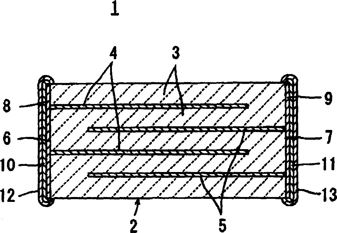
Embodiment 1
[0107] Embodiment 1 adopts BaTiO 3 ABO used as main ingredient 3 , using Y 2 o 3 , NiO, MnO 2 and SiO 2 As an example of added ingredients.
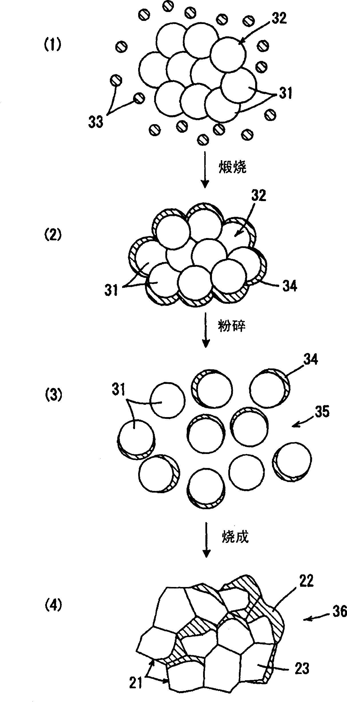
[0108] First as an ABO 3 The starting material was prepared TiCl 4 and Ba(NO 3 ) 2 , using oxalic acid to barium titanyl oxalate (BaTiO(C 2 o 4 )·4H 2 O) form it was precipitated and a precipitate was obtained. The precipitate was heated and decomposed with a spray dryer at 1000 °C to synthesize BaTiO 3 , to prepare BaTiO 3 Condensate.
[0109] Then the BaTiO 3 Agglomerates were crushed for 5 hours. The pulverized BaTiO was observed by electron microscopy (SEM) 3 After confirming the aggregates, more than 70% of the particles were aggregates composed of 4 to 8 primary particles.
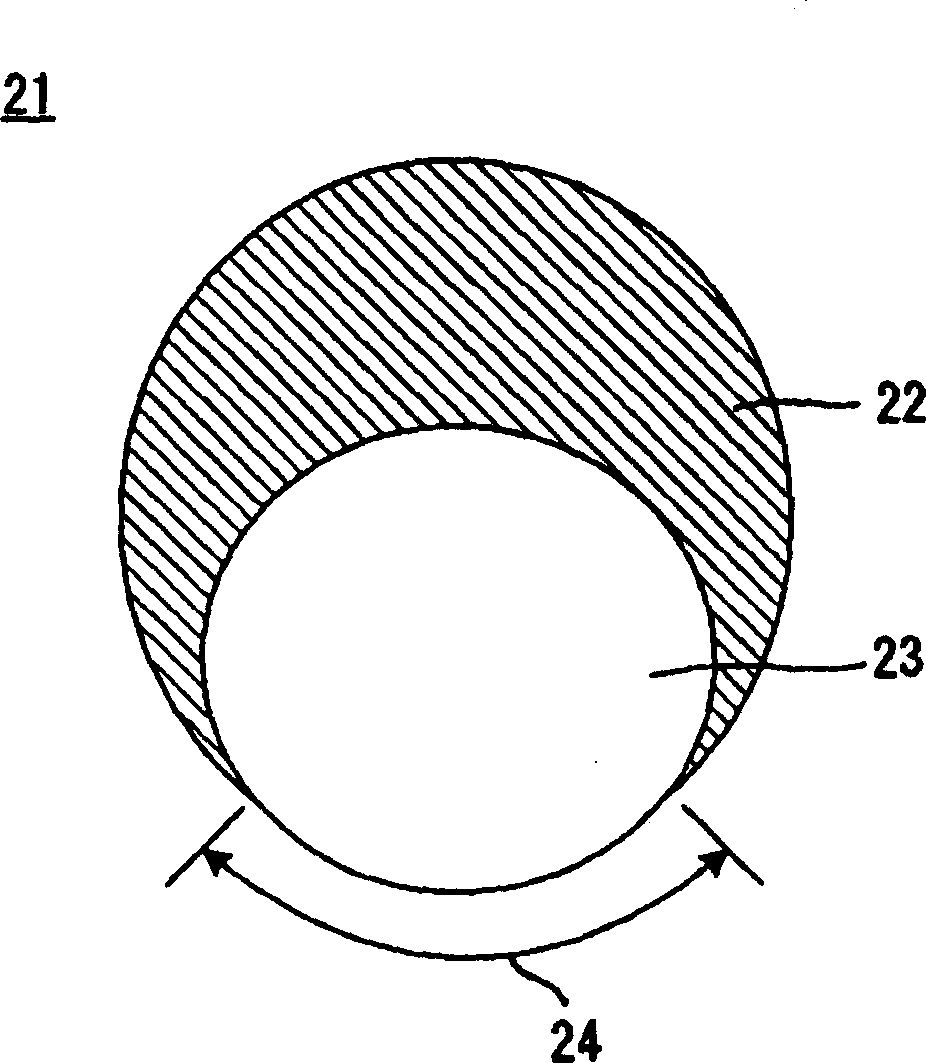
[0110] Then 1 mole of Y 2 o 3 With 100 moles of the above pulverized BaTiO 3 Agglomerates are mixed and calcined at 1000°C for 2 hours to obtain BaTiO in which Y is solid-dissolved on the surface 3 Condensate. This BaTiO 3 The condensate...
Embodiment 2
[0133] In embodiment 2, be to adopt (Ba0.95 Ca 0.05 )(Ti 0.99 Zr 0.01 )O 3 As the main ingredient ABO 3 , using Y 2 o 3 , MgO, MnO 2 and SiO 2 As an example of added ingredients.
[0134] First as an ABO 3 The starting material was prepared from BaCO 3 , CaCO 3 、TiO 2 and ZrO 2 , weigh these substances according to the predetermined composition, and then calcinate the mixture at a temperature of 1150 ° C to synthesize (Ba 0.95 Ca 0.05 )(Ti 0.99 Zr 0.01 )O 3 , and at the same time a condensate was obtained.
[0135] It was confirmed by electron microscope (SEM) observation of such aggregate particles that about 70% or more of the particles were aggregates composed of 4 to 8 primary particles.
[0136] Then adopt the same method as in Example 1, Y 2 o 3 Mix in the above-mentioned condensate, and obtain Y solid-dissolved on the surface part through calcining (Ba 0.95 Ca 0.05 )(Ti 0.99 Zr 0.01 )O 3 Condensate. This aggregate is found through X-ray diffrac...
Embodiment 3-1
[0170] In addition to synthesis (Ba 0.80 Ca 0.20 )(Ti 0.996 f 0.004 )O 3, various raw material powders are mixed, make relative to 100 moles of this aggregate, except adding 0.5 moles of Sm and 0.5 moles of Tm, operate in the same way as in Example 2, and obtain Sm and Tm in the surface part solid solution (Ba 0.80 Ca 0.20 )(Ti 0.996 f 0.004 )O 3 powder.
[0171] Then mix each raw material powder, make relative to 100 mol (Ba 0.80 Ca 0.20 )(Ti 0.996 f 0.004 )O 3 The powder was added with 0.2 mole of Gd, 0.2 mole of Yb, 0.3 mole of Mn, 1.5 mole of Cr, and 1.6 mole of sintering aid composed of Si-Li-O (Si:Li=0.9:0.1), and obtained a mixture as a dielectric ceramic powder powder.
[0172] Furthermore, using the mixed powder described above, a multilayer ceramic capacitor was manufactured in the same manner as in Example 1. In addition, the obtained multilayer ceramic capacitors were also evaluated under the same conditions as above. The evaluation results are show...
PUM
| Property | Measurement | Unit |
|---|---|---|
| particle size | aaaaa | aaaaa |
| Curie point | aaaaa | aaaaa |
Abstract
Description
Claims
Application Information