

Unifilar tungsten arc spray equipment
An arc spraying and tungsten electrode technology, which can be used in spraying devices, liquid spraying devices, etc., can solve the problem of high cost
- Summary
- Abstract
- Description
- Claims
- Application Information
AI Technical Summary
Problems solved by technology
Method used
Image

Examples
specific Embodiment approach 1
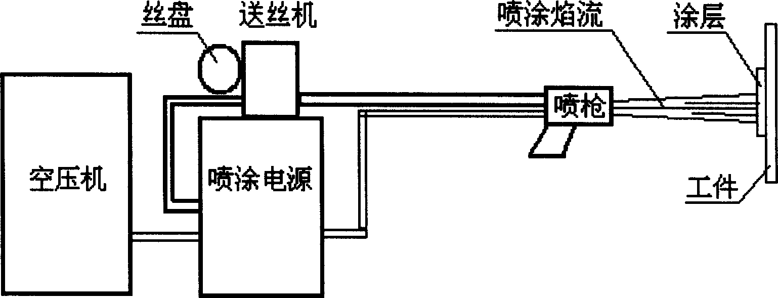
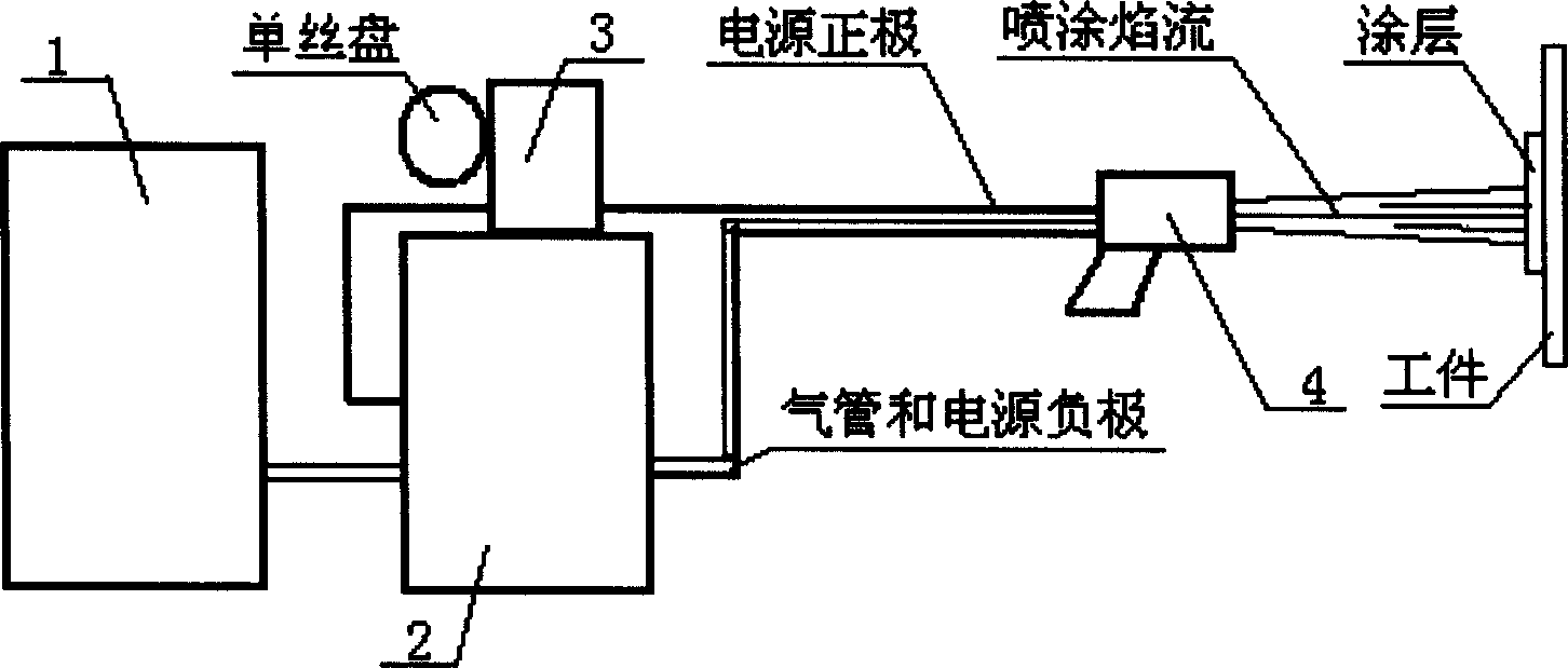
[0006] Embodiment 1: The principle of the present invention is to use a tungsten electrode (connected to the negative pole of the power supply) and a single spraying wire (connected to the positive pole of the power supply), establish an arc through high-frequency arc ignition, melt the spraying wire, and accelerate the spraying to the A new type of arc spraying device on the workpiece. The spraying wire described in the present invention can be a metal solid core wire or a drug-cored tubular wire. Since the temperature of the arc is twice as high as that of the flame, the device of the present invention is particularly suitable for It is based on the spraying of ceramic core tubular wire (metal skin wrapping ceramic powder), thus realizing the purpose of preparing ceramic coating by arc spraying method with low cost and high performance coating quality. The device of the present invention includes an air compressor 1, a spraying power supply 2, a wire feeder 3, and a spraying ...
specific Embodiment approach 2
[0010] Embodiment 2: The spraying process of this embodiment is as follows: 1. Workpiece surface roughening: the surface of the workpiece to be sprayed is cleaned to remove oil, lathe processing or polishing to remove defects and fatigue layers, and then roughen the surface with sandblasting. 2. On-line: The spraying gun, wire feeder, and air compressor described in the first specific embodiment are connected to the spraying power supply, and the spraying wire is threaded into the wire feeder and sent into the spraying gun, see image 3shown. 3. Adjust spraying process parameters: pre-adjust atomizing compressed air pressure and flow, spraying voltage, spraying current, arc current, wire feeding speed. The adjustment of this process parameter is related to the material type of the sprayed wire and the specification diameter of the sprayed wire. The material and the diameter are different, and the corresponding process parameters are also different: the sprayed wire selected in...
specific Embodiment approach 3
[0011] Specific embodiment three: this embodiment is the spraying process of crankshaft:
[0012] 1. Conditions: The sprayed product is a worn imported automobile crankshaft, the material is ductile iron, the maximum wear depth is 0.5mm, the outer diameter of the crankshaft has become elliptical, and the size needs to be restored.
[0013] 2. Spraying process: degrease and decontaminate the crankshaft first, grind the fatigue layer and ovality of the outer diameter of the crankshaft, then sandblast and roughen it, and install the crankshaft on the special worktable for crankshaft spraying with rotating function. Connect the equipment and adjust the various process parameters required for spraying. The spraying voltage is 25V; the gas pressure of compressed air is 0.65MPa; the arc blowing current is 10A; the spraying current is 100A; the wire feeding speed is 1m / min; the diameter of the spraying wire is Φ1. 5mm. After everything is ready, you can start spraying.
[0014] 3. C...
PUM
| Property | Measurement | Unit |
|---|---|---|
| Thickness | aaaaa | aaaaa |
| Thickness | aaaaa | aaaaa |
Abstract
Description
Claims
Application Information