Biomass and powder coal mixed combustion and biomass recombusting and denitrating combustion apparatus

A combustion device and biomass technology, applied to the combustion of block fuel and liquid fuel, the combustion of block fuel and gaseous fuel, the combustion of block fuel and powder fuel, etc., which can solve the problem of ineffective utilization of biomass Material energy, large NOx emissions, reduction of NOx emissions, biomass reburning and denitrification, etc.

Inactive Publication Date: 2005-09-28
HARBIN INST OF TECH
View PDF0 Cites 8 Cited by
  • Summary
  • Abstract
  • Description
  • Claims
  • Application Information

AI Technical Summary

Problems solved by technology

[0004] The present invention is aimed at the disadvantages of the existing combustion devices that have large NOx emissions and cannot effectively utilize biomass energy, thereby providing a biomass-coal composite that can efficiently utilize biomass energy while greatly reducing NOx emissions. Combustion and biomass reburning denitrification combustion device, which includes a furnace 1, a pulverized coal main combustion area 1-1 is arranged in the furnace 1, and burner thick-thin nozzles are installed on the four corners of the furnace chamber of the pulverized coal main combustion area 1-1 2. A biomass burner nozzle 3-1 is also installed on the side wall or four corners of the furnace 1

Method used


Image

  • Biomass and powder coal mixed combustion and biomass recombusting and denitrating combustion apparatus
  • Biomass and powder coal mixed combustion and biomass recombusting and denitrating combustion apparatus
  • Biomass and powder coal mixed combustion and biomass recombusting and denitrating combustion apparatus

Examples


specific Embodiment approach 1

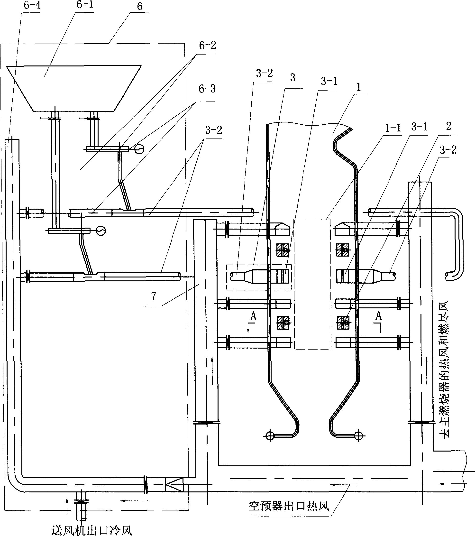
[0006] Specific implementation mode one: refer to figure 1 , Figure 4 , the present embodiment includes a furnace 1, a pulverized coal main combustion zone 1-1 is arranged in the furnace 1, and a burner thick-thin spout 2 is installed on the four corners of the furnace furnace of the pulverized coal main combustion zone 1-1, and the furnace 1 A biomass burner spout 3-1 is also installed on the side wall or four corners. The biomass burner nozzle 3-1 in this embodiment is installed on the furnace side wall of the pulverized coal main combustion zone 1-1. The biomass burner nozzle 3 - 1 and the biomass delivery connecting pipe 3 - 2 connected thereto together form the biomass burner 3 . The biomass burner 3 is connected to the pneumatic conveying system 6 of the biomass fuel, and the pneumatic conveying system 6 of the biomass fuel includes a biomass fuel hopper 6-1, a biomass fuel feeder 6-2, and a mixer 6-3 And pneumatic conveying pipeline 6-4, described biomass fuel hoppe...

specific Embodiment approach 2

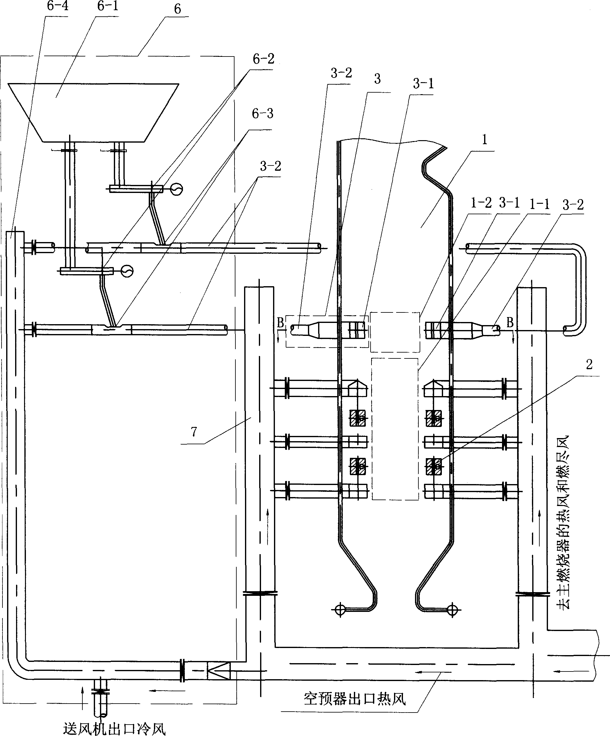
[0008] Specific implementation mode two: refer to figure 2 , in this embodiment, the upper part of the biomass combustion zone 1-1 is a reduction zone 1-2. The difference between this embodiment and the first embodiment is that the biomass burner nozzle 3-1 is installed in the reduction zone 1-2 on the furnace side wall, refer to Figure 5 , At this time, the reduction zone 1-2 is a biomass combustion zone.

[0009] When the primary air pulverized coal airflow is sent into the furnace 1, it is divided into a dense coal pulverized airflow and a light coal pulverized airflow respectively by the thick and thin burner nozzles in the horizontal direction. The ignition heat of the airflow increases the speed of flame propagation, which can ensure the stable combustion of pulverized coal in the main combustion zone 1-1, and the combustion of pulverized coal in the airflow of concentrated pulverized coal and airflow of light coal pulverized is deviated from the stoichiometric ratio,...

specific Embodiment approach 3

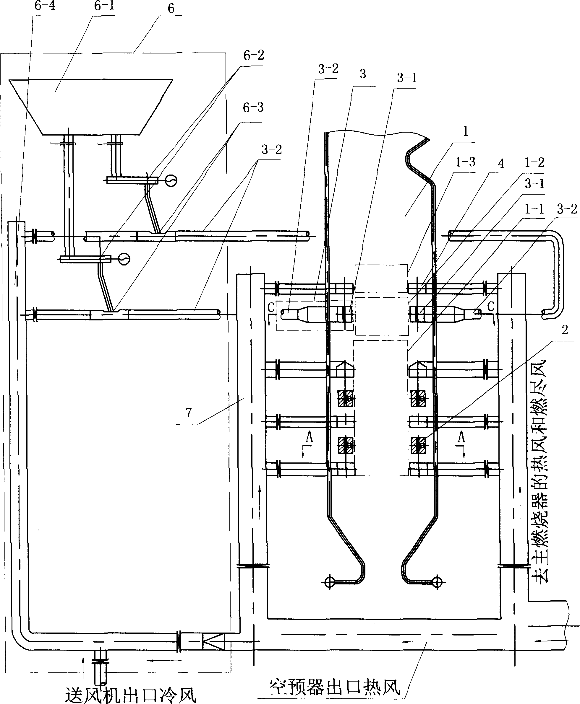
[0010] Specific implementation mode three: refer to image 3 , the upper part of the reduction zone 1-2 is the burnout zone 1-3. The difference between this embodiment and the second embodiment is that the burnout air nozzle is installed on the furnace side wall or four corners of the burnout zone 1-3 4. The overburning air nozzle 4 is in communication with the air supply duct 7; refer to Figure 6 , The biomass burner spout 3-1 is installed on the four corners of the hearth of the reduction zone 1-2.

[0011] The overfire air nozzle 4 is mainly used to provide oxygen for the burnout of biomass fuel and pulverized coal. The burn-out air is sent into the burn-out area 1-3 in the upper part of the furnace. Since some air is sprayed into this area from the nozzle 4, it can promote the further combustion of biomass fuel and coal powder particles, and at the same time reduce the air volume in the lower furnace, so that The pulverized coal and biomass in the lower furnace are burn...


PUM


Abstract

The present invention is one burning apparatus for the composite burning of biomass and coal powder and re-burning and denitrifying of biomass. The burning apparatus includes hearth, main coal powder burning area inside the hearth, main nozzles and biomass nozzles installed on the four corner of the hearth. The present invention has the following advantages: lower NOx exhaust rate, burning out of biomass fuel, large scale utilization of biomass, reduced room temperature CO2, and lowered SOx exhaust and simple apparatus structure.

Description

Technical field: [0001] The invention relates to a combustion device. Background technique: [0002] Combustion of pulverized coal is an important source of nitrogen oxides (NOx). Usually, the NOx emission of anthracite and lean coal boilers is 900-1200mg / m 3 , the NOx emission of the bituminous coal boiler is 600~850mg / m 3 , the NOx emission of lignite-fired boilers is 400-600mg / m 3 . Nitrogen oxide (NOx) is the main source of air pollution. In addition to forming acid rain and destroying the ecological environment, it can also form photochemical smog, which is harmful to human health. In addition, SOx emissions from coal-fired boilers are high. Coal combustion is one of the main sources of NOx. In order to control the increasingly serious NOx pollution, the new "Emission Standards of Air Pollutants for Thermal Power Plants" (GB13223-2003) issued by the State Environmental Protection Administration and the General Implemented on January 1, the "Emission Standard" is mo...

Claims


Application Information

Patent Timeline
Patent Type & Authority Applications(China)
IPC IPC(8): F23C1/00F23C5/08F23C7/00F23K1/00F23K3/00
Inventor 李争起朱群益赛俊聪孙绍增吴少华
Owner HARBIN INST OF TECH
Why Eureka
Try Eureka