Method for improving optical-fiber type complete optical buffer register characteristic

An optical buffer, optical fiber technology, applied in electromagnetic wave transmission systems, electrical components, transmission systems, etc., can solve problems such as increasing the bit error rate of communication links, limiting the buffer period, and unable to receive signals correctly.

Inactive Publication Date: 2005-12-21
BEIJING JIAOTONG UNIV
View PDF0 Cites 10 Cited by
  • Summary
  • Abstract
  • Description
  • Claims
  • Application Information

AI Technical Summary

Problems solved by technology

Another important issue is: when SOA is used as an element to generate nonlinear phase shift, it is inevitable to introduce nonlinear cross-gain modulation, which will cause the signal optical power imbalance in the clockwise and counterclockwise directions, which will lead to the transmission of the output signal Ratio (the ratio of opt

Method used


Image

  • Method for improving optical-fiber type complete optical buffer register characteristic
  • Method for improving optical-fiber type complete optical buffer register characteristic
  • Method for improving optical-fiber type complete optical buffer register characteristic

Examples


Embodiment 1

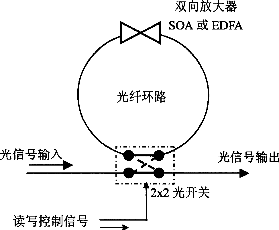
[0028] for figure 1 Shown single-ring all-optical buffer, the specific implementation scheme sees Figure 8 and Figure 9 . Figure 8 It is the embodiment of suppressing self-excited and noise in the fiber ring. First, an adjustable attenuator VOA is introduced into the fiber ring, and the optical power in the ring is adjusted in real time according to the gain change of the amplifier, so as to ensure that the net gain in the fiber ring is 1 during the whole process of buffer operation, which can effectively avoid The occurrence of self-excited phenomena. In order to achieve the purpose of suppressing noise, the input and output power of the wavelength division multiplexer placed on both sides of the amplifier is 15dBm (when the DC optical power is greater than 15dBm, the optical amplifier will work in the saturated amplification area, and it is no longer necessary to continue to increase the DC optical power. The direct current light of great significance) is used as the ...

Embodiment 2

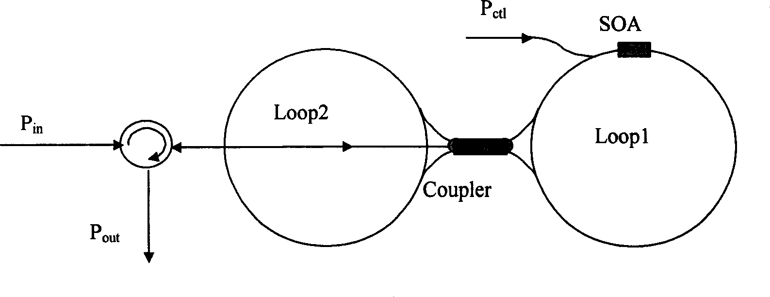
[0031] for image 3 Described double-ring all-optical buffer, specific implementation scheme sees Figure 10 . Figure 10 It shows an example of placing an adjustable attenuator in the double ring to avoid self-excitation, and adjusts the optical power in the ring in real time according to the gain change of the amplifier, so as to ensure that the net gain in the optical fiber ring is 1. In this way, the self-excitation phenomenon can be effectively avoided. The traditionally used positive-phase control light pulse is modulated according to the reverse-phase modulation method described in the summary of the invention into Figure 7 The format in the example is used to increase the transfer ratio of the buffer output signal. A DC optical base with a power of 5dBm for noise suppression is generated by adding equal-power DC bias to the control light pulse. Its wavelength is the same as that of the control light, and it is introduced into the optical fiber ring together with th...

Embodiment 3

[0034] For this type of all-optical buffer of "reflective optical fiber (FP cavity)+optical switch" (through type), see the specific implementation plan Figure 11 and Figure 12 . For this type of pass-through all-optical buffer, the logic operations of "writing" and "reading" of data are respectively completed by the SOAs in the left and right rings. Figure 11 is a schematic diagram for generating anti-phase controlled light pulses for suppressing noise and improving transmission ratio. In the figure, the DC optical pedestal with a power of 12dBm is generated by another tunable light source, and its wavelength is different from that of signal light and control light, and is used to suppress noise; the conventionally used positive phase control light pulse is used as described in the summary of the invention The inverse modulation method of the inverse modulation is Figure 7 The format in the example is used to increase the transfer ratio of the buffer output signal. Th...


PUM


Abstract

One or two pieces of adjustable pad are added to optical fiber loop. One DC light base is added i.e. continuous light in power 0dBm - 15dBm is introduced to light amplifier in optical fiber loop. When magnified signal is departed from the amplifier the light base is exported from the optical fiber loop by wavelength division multiplexer. The DC light base nay be generated by another DC light source, and its wavelength is different from wavelength of signal light and control light. A wavelength division multiplexer introduces the wavelength of DC light source in or out of optical fiber loop. Adding DC bias in same power directly onto the control light pulse in use for controlling read/write of buffer generates a DC light base in same wavelength. Inventory controlled optical pulse is adopted. Features are: restraining net gain of fiber loop, the added pad makes loop not generate self-excitation; DC light base restrains noise; and inventory controlled optical pulse raises SNR.

Description

technical field [0001] The patent of the present invention relates to a method for improving the performance of an optical fiber type all-optical buffer. The invention belongs to the field of optical information processing components. Background technique [0002] The all-optical buffer not only caches optical signals, but also uses optical signals instead of electrical signals to control read and write operations. It is the basic component of optical information processing, and can be widely used in optical fiber communication, optical signal (information) processing, optical packet switching, all-optical routers, optical computing and other fields. With the construction of high-speed all-optical network, the all-optical network is transitioning from an optical transport network with wavelength as granularity to an optical switching network with packet granularity. Optical packet switching is essentially a store-and-forward technology. The all-optical buffer is the key de...

Claims


Application Information

Patent Timeline
Inventor 李亚捷吴重庆刘爱明
Owner BEIJING JIAOTONG UNIV
Why Eureka
Try Eureka