

Multi-pulse superimposing amplifier and femtosecond laser parameter chirped-pulse amplification laser
A multi-pulse and amplifier technology, applied to lasers, laser components, phonon exciters, etc., can solve the problems of inability to adjust the time length and spectrum width of pump light, complex structure, etc., and achieve supercontinuum stability and narrow spectrum , the effect of increasing flexibility
- Summary
- Abstract
- Description
- Claims
- Application Information
AI Technical Summary
Problems solved by technology
Method used
Image

Examples
Embodiment 1
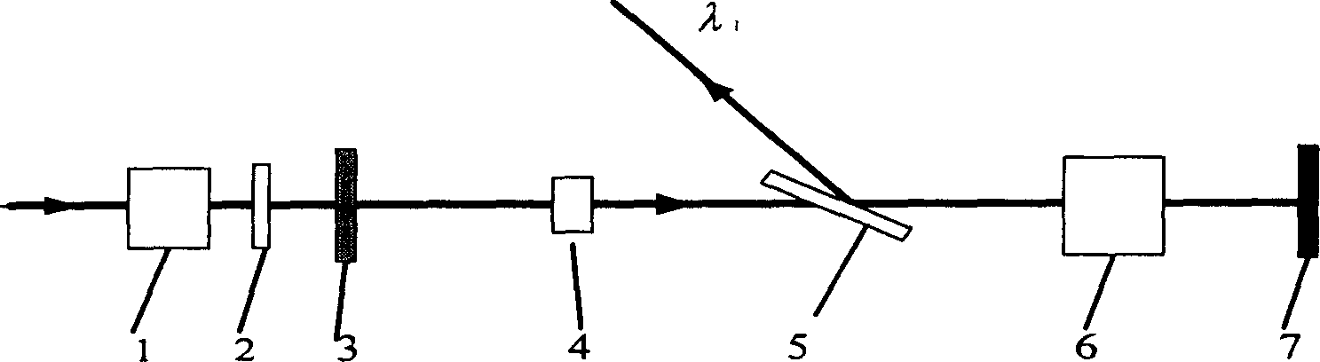
[0031] The structure of the multi-pulse superposition amplifier described in this embodiment is as follows figure 1As shown, it is composed of Faraday 1, 45° rotor 2, first high reflection mirror 3, gain medium I 4, dielectric film polarizer 5, Pockels cell 6 and second high reflection mirror 7, each of the above optical elements can be Bought from the market. Among the above optical components, the spectral gain bandwidth of the gain medium I4 is about 0.5nm, and its amplified peak wavelength matches the central wavelength of the pulse entering the resonator; the Pockels cell 6 uses a KDP crystal, and its λ / 4 delay voltage is 700 Volt. Faraday 1 and 45° rotor 2 form an optical switch for the ultrashort pulse train to enter the resonator, and the first high reflection mirror 3, gain medium I4, dielectric film polarizer 5, Pockels cell 6 and second high reflection mirror 7 form a pair A resonant cavity in which ultrashort optical pulse trains perform pulse superposition and s...
Embodiment 2
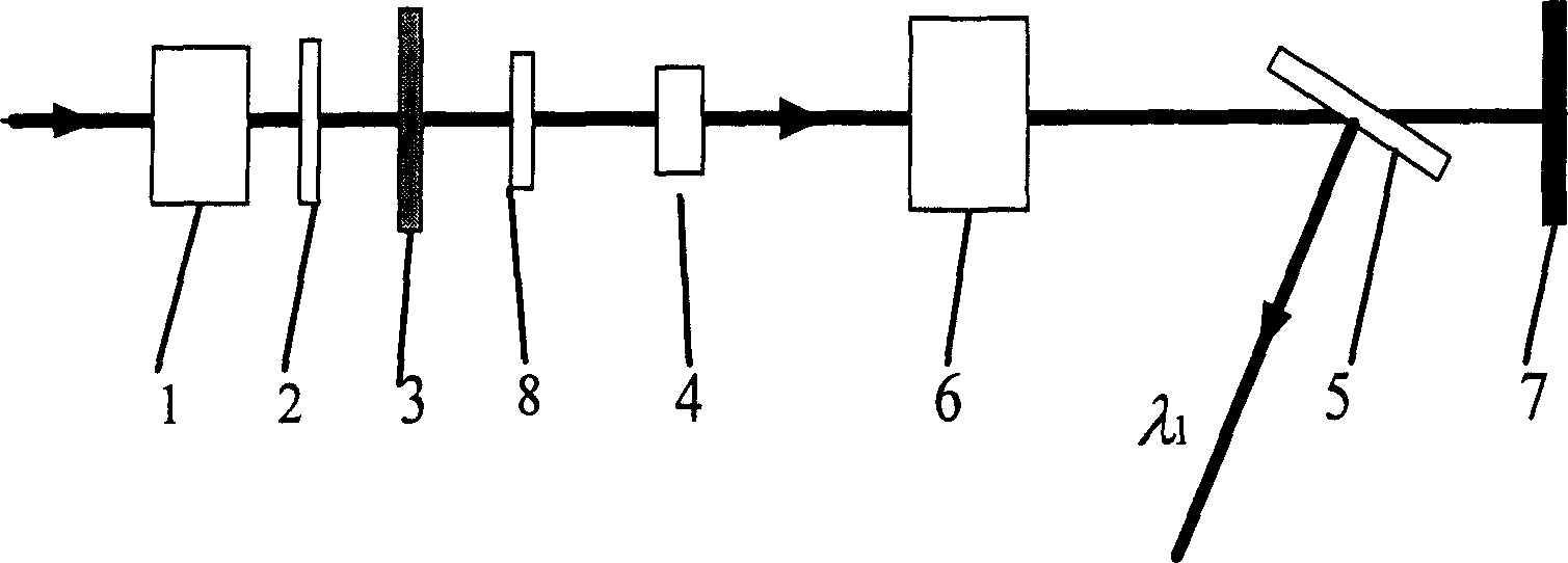
[0035] The structure of the multi-pulse superposition amplifier described in this embodiment is as follows figure 2 As shown, the difference with Embodiment 1 is: (1) an etalon 8 is added, and the etalon is a constituent element of a resonant cavity, which performs spectral filtering on an ultrashort optical pulse, and its passband bandwidth is 0.02nm, and the transmittance The peak center wavelength is 1053nm. (2) The etalon 8, the gain medium I4, the Pockels cell 6 and the dielectric film polarizer 5 are sequentially placed between the two end faces of the resonant cavity formed by the first high reflection mirror 3 and the second high reflection mirror 7.
[0036] The structure of the femtosecond laser parametric chirped pulse amplification laser described in this embodiment is as follows Figure 6 As shown, the difference from Embodiment 1 is: (1) beam splitter 10 will input the center wavelength as λ 0 The ultrashort pulse train is divided into a center wavelength λ 0...
Embodiment 3
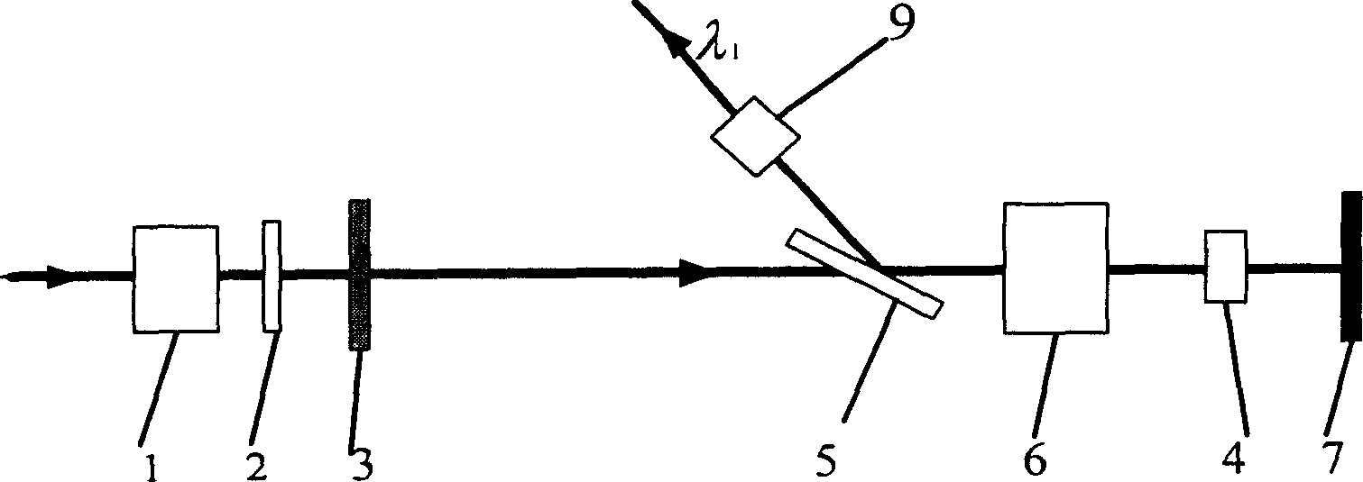
[0038] The structure of the multi-pulse superposition amplifier described in this embodiment is as follows image 3 As shown, the difference from Embodiment 1 is: (1) gain medium II9 is arranged on the derivation optical path of dielectric film polarizer 5, which further amplifies the superimposed flat-top pulse derived from the resonator, and its spectral gain bandwidth is 0.5 nm. (2) Dielectric film The polarizer 5 , the Pockels cell 6 and the gain medium I4 are sequentially placed between the two end faces of the resonant cavity formed by the first high reflection mirror 3 and the second high reflection mirror 7 .
[0039] The structure of the femtosecond laser parametric chirped pulse amplification laser described in this embodiment is as follows Figure 7 As shown, the difference with Embodiment 1 is: (1) inject 30 central wavelengths to the multi-pulse superposition amplifier 12 and be λ 1 The ultrashort pulse of the multi-pulse superposition amplifier is adjusted to...
PUM
 Abstract
Description
Claims
Application Information