
Vibration wire type digital memory sensor

A sensor and vibrating wire technology, which is applied in the field of sensors, can solve the problems of affecting the test accuracy, slow test speed, and inability to calculate, and achieve the effect of high test accuracy, little influence of gravity, and simple structure

Inactive Publication Date: 2006-03-08
长沙金码测控科技股份有限公司
View PDF0 Cites 5 Cited by
  • Summary
  • Abstract
  • Description
  • Claims
  • Application Information

AI Technical Summary

Problems solved by technology

[0002] The vibrating wire sensor in the prior art is a sensor made according to the fact that the natural frequency of the steel string fixed at both ends is proportional to the tension, and the tension of the steel string is proportional to the deformation it receives. It is widely used to detect physical quantities such as strain, stress, pressure, and displacement of objects. Because of its guaranteed material and direct output frequency signal, there is no zero drift and good long-term stability. Therefore, it is used in water conservancy and hydropower, railways, transportation, and construction. and other fields have been widely used; but the current vibrating wire sensor has the following disadvantages: ①The output of the sensor is the measured frequency value, and the measured physical quantity of the object must be converted according to the calibration curve, and the test speed is slow. The technical level is high; ②When a large number of sensors are buried in the engineering structure for long-term quality monitoring, the sensor transmission cable is prone to contamination or interruption, resulting in the loss of the sensor number and calibration parameters, and even the measurement frequency value cannot be calculated accordingly. Invalid data conditions for physical quantities
In view of the above problems, there are improvers in the prior art who integrate complex processing circuits and memory with other components of the sensor. Such sensors have the disadvantages of complex structure, large volume, and heavy weight, which is not conducive to the installation and disassembly of testers. , especially when multiple sensors are installed on a large object to be tested, it will bring a great impact of gravity on the object to be tested, thus affecting the accuracy of the test

Method used


Image

  • Vibration wire type digital memory sensor
  • Vibration wire type digital memory sensor

Examples


Embodiment Construction

[0020] The present invention will be described in further detail below in conjunction with the accompanying drawings.

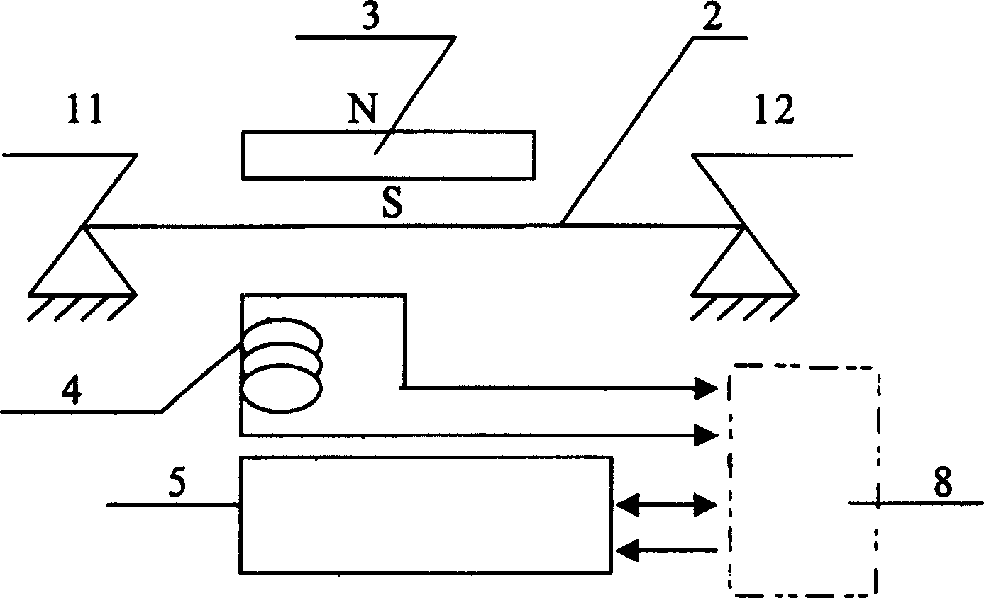
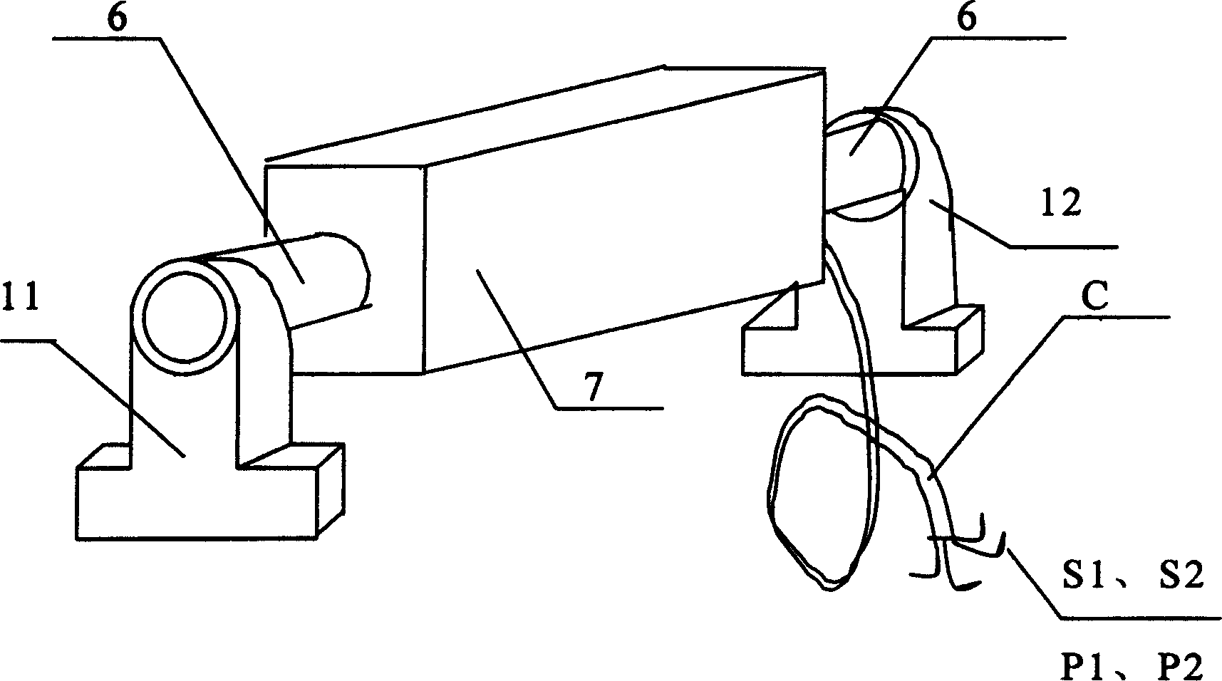
[0021] Such as figure 1 and figure 2 As shown, the vibrating wire type digital memory sensor of the present invention comprises a left end seat 11, a right end seat 12 and a sealed casing 7 located between the left end seat 11 and the right end seat 12, and a The left end seat 11 and the right end seat 12 are tensioned steel strings 2, permanent magnets 3, induction coils 4 and memory 5, which are the fulcrums. The right end seat 12 is connected, and the permanent magnet 3 and the induction coil 4 are respectively packaged on opposite sides of the steel string 2 perpendicularly to the steel string 2 . Among them, the induction coil 4 is connected with the secondary instrument 8 outside the sensor, which is responsible for receiving the input test pulse and outputting the magnetic excitation force, while the steel string 2 is excited by the magnetic excitat...


PUM


Abstract

This invention discloses a string vibration type memory sensor, which contains left end base, right end base, sealed casing with enclosed tensioned steel string using left and right end base as support point, permanent magnet and induction windings, a memory, said memory and induction windings respectively connected with secondary instrument in outside of sensor. Said invention not only directly detects the needed physical quantity but also transmits long distance with advantages of simple structure, small volume, light and high measurement precision.

Description

technical field [0001] The invention mainly relates to the field of sensors, in particular to a vibrating wire digital memory sensor. Background technique [0002] The vibrating wire sensor in the prior art is a sensor made according to the fact that the natural frequency of the steel string fixed at both ends is proportional to the tension, and the tension of the steel string is proportional to the deformation it receives. It is widely used to detect physical quantities such as strain, stress, pressure, and displacement of objects. Because of its guaranteed material and direct output frequency signal, there is no zero drift and good long-term stability. Therefore, it is used in water conservancy and hydropower, railways, transportation, and construction. and other fields have been widely used; but the current vibrating wire sensor has the following disadvantages: ①The output of the sensor is the measured frequency value, and the measured physical quantity of the object must...

Claims


Application Information

Patent Timeline
Patent Type & Authority Applications(China)
IPC IPC(8): G01D5/00G01D5/48G01L1/10G01B17/04G01B17/00
Inventor 杨金喜刘克明
Owner 长沙金码测控科技股份有限公司
Learn More