Water body pollution laser induction fluorescence remote-measuring method

A laser-induced fluorescence and water pollution technology, applied in the direction of fluorescence/phosphorescence, optics, nonlinear optics, etc., can solve problems such as the influence of fluorescence intensity

Inactive Publication Date: 2006-05-17
ANHUI INST OF OPTICS & FINE MECHANICS - CHINESE ACAD OF SCI
View PDF0 Cites 12 Cited by
  • Summary
  • Abstract
  • Description
  • Claims
  • Application Information

AI Technical Summary

Problems solved by technology

[0004] The purpose of the present invention is to solve the impact of the ambient light intensi

Method used


Image

  • Water body pollution laser induction fluorescence remote-measuring method

Examples


Embodiment Construction

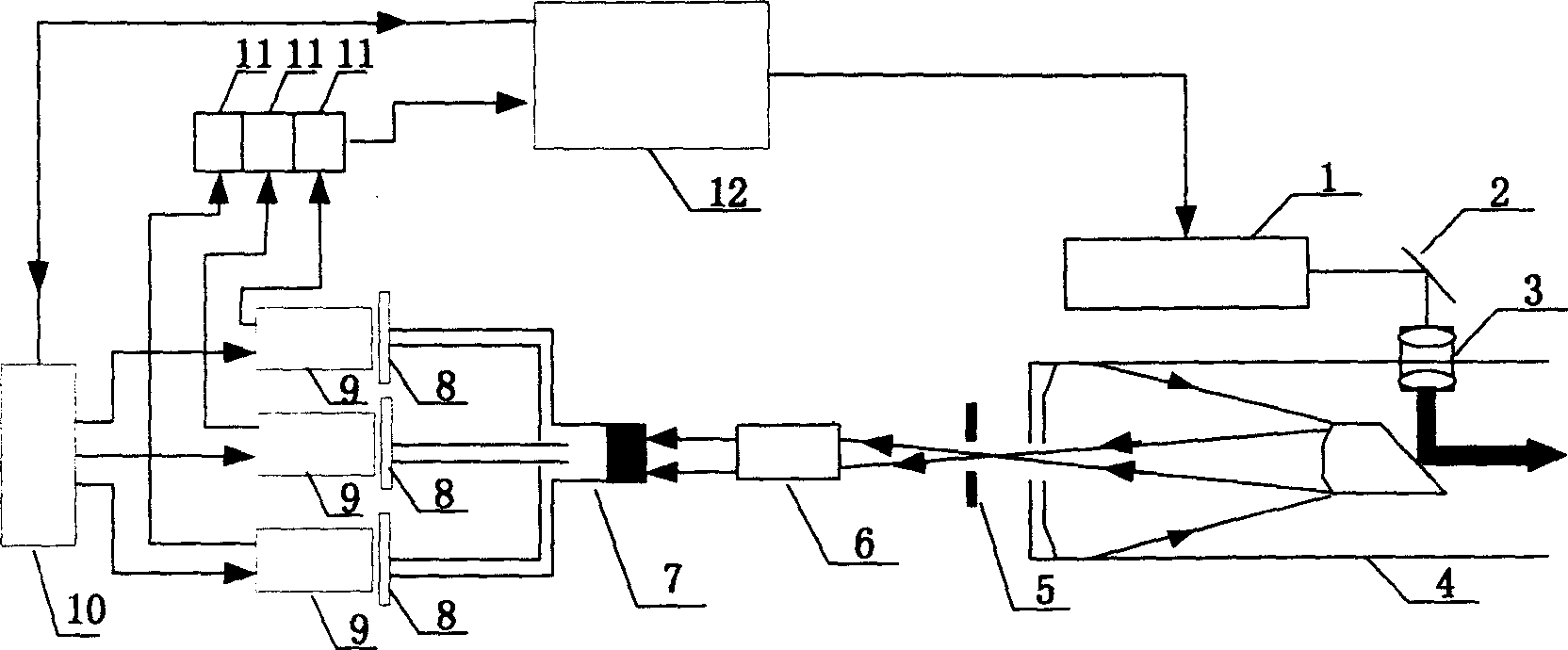
[0011] See Figure 1. Labels in the figure:

[0012] 1. Laser light source system

[0013] 2. Beam reflection system

[0014] 3. Beam expander system

[0015] 4. Receiving / transmitting telescope

[0016] 5. Light bar

[0017] 6. Beam collimator

[0018] 7. Optical fiber bundle

[0019] 8. Optical filter

[0020] 9. Photomultiplier tube

[0021] 10. Photomultiplier tube high-voltage power supply and gate control device

[0022] 11. Time gate current integration circuit

[0023] 12. For control, acquisition processing and display system

[0024] As can be seen from the figure, the device components of the present invention are formed.

[0025] The laser-induced fluorescence telemetry method for water pollution is to obtain the excitation light pulse of 355nm by tripling the frequency of the Nd:YAG laser, expand and collimate the beam through the transmitting telescope, and irradiate the measured object—the surface of the polluted water body, and the fluorescence emitte...


PUM


Abstract

The present invention discloses a laser induced fluorescence remote measuring method for water body pollution. It is characterized by that the equipment for implementing said method includes the following several components: Nd:YAG laser, receiving telescope, several fibre bundles, optical filters, photoelectric multiplier and gating device, etc. Said invention also provides the concrete connection mode of all the above-mentioned components and the working principle of said remote measuring method.

Description

technical field [0001] The invention belongs to the field of laser measurement, in particular to a method for measuring water pollution by ultraviolet laser induced fluorescence. Background technique [0002] When a substance is irradiated by light, it will emit fluorescence, and different substances have their specific fluorescence spectrum characteristics. Fluorescence spectral features can identify the species and concentration of the excited species. Using this principle, remote sensing of water pollution can be realized. [0003] The prior art method for measuring water body pollution by ultraviolet laser-induced fluorescence is to use Nd:YAG laser triple frequency 355nm wavelength excitation light with a pulse repetition frequency of 10 Hz. The backscattered fluorescent signal of the water body is received through the Cassegrain telescope, and the transmission and reception adopts a coaxial method. After being coupled into the monochromator through an optical fiber, ...

Claims


Application Information

Patent Timeline
IPC IPC(8): G01N21/63G01N21/64G01N21/65G02F1/00
Inventor 张玉钧刘文清刘建国赵南京李宏斌胡明勇丁志群王志刚杨立书崔志成魏庆农谢品华陆亦怀王亚萍张长秀
Owner ANHUI INST OF OPTICS & FINE MECHANICS - CHINESE ACAD OF SCI
Why Eureka
Try Eureka