Basal plate cleaning system and method

A technology for cleaning systems and substrates, applied in cleaning methods and utensils, cleaning methods using liquid, chemical instruments and methods, etc. Efficiency reduction, low surface tension effect

Inactive Publication Date: 2006-07-12
IND TECH RES INST
View PDF0 Cites 13 Cited by
  • Summary
  • Abstract
  • Description
  • Claims
  • Application Information

AI Technical Summary

Problems solved by technology

[0005] In the prior art, the detection and analysis of pollutants includes the use of a quartz crystal microbalance system to measure the change of the amount of non-gas pollutants present in the sample stream. This system can be used to monitor the cleaning and cleaning of supercritical fluids. Extraction procedure; however, no mention is made of other methods of measuring cleaning efficiency other than using a quartz crystal microbalance system
[0006] In the cleaning part about increasing the ultrasonic wave and nozzle device, the related technology is to arrange several nozzles for pre-washing, a low-pressure chamber and an acoustic wave generating device for expanding the compressed liquid in the cleaning tank, and a forced stirring device utilizing rotating wings to Achieving a strong cleaning effect with foaming; however, this device must use the forced stirring of the sound wave generating device and the rotating wing to achieve the cleaning effect, which is really inconvenient

Method used


Image

  • Basal plate cleaning system and method

Examples


Embodiment 1

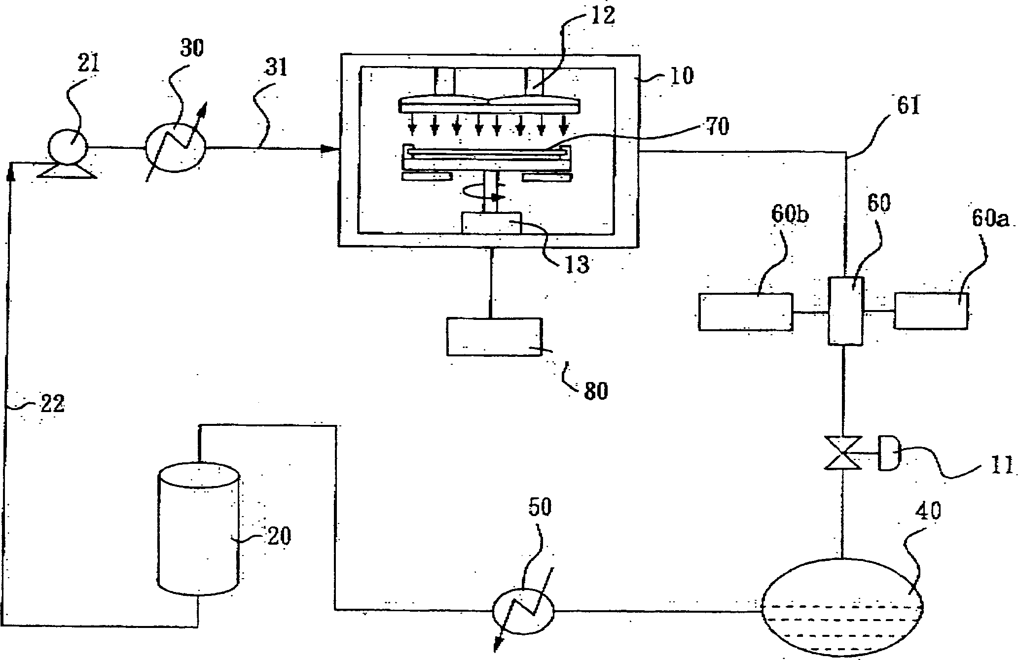
[0029] This embodiment illustrates the use of the substrate cleaning system device of the present invention, please refer to figure 1 Device system diagram.

[0030] figure 1 There is respectively a closed cleaning chamber 10 in it; a lotion supply device 80; a carbon dioxide liquid storage device 20; a pressure control device (delivery pump) 21; a temperature control device 30; and an online monitoring device 60; Device 80 is to supply a surfactant, carbon dioxide liquid storage device 20 is to join with pressure control device 21 with a connecting pipe 22, pressure control device 21 is connected with temperature control device 30, and temperature control device 30 is connected with a through pipe 31 again. Connect with the airtight cleaning chamber 10, send a supercritical carbon dioxide mixed liquid from the carbon dioxide liquid storage device 20 into the airtight cleaning chamber 10, and utilize a plurality of ultrasonic nozzles 12 in the airtight cleaning chamber 10 to ...

Embodiment 2

[0033] Using the apparatus of Embodiment 1, the operation mode of the substrate cleaning system of the present invention will be described.

[0034]First place a substrate 70 (such as a wafer) into the airtight cleaning chamber 10, then use the delivery pump 21 to pressurize the liquid carbon dioxide from the liquid-phase carbon dioxide storage tank 20 to a pressure above 73 atm, and then heat the carbon dioxide through the heater 30 Above the critical temperature of 31.1°C, the liquid carbon dioxide in the mixed liquid reaches a supercritical state, and then the mixed liquid is sent into the airtight cleaning chamber 10. At this time, together with the surfactant from the lotion supply device 80, co-solvent or a chelate A mixed liquid formed by the mixture is sprayed onto the surface of the substrate 70 by several ultrasonic vibrators and movable nozzles 12, and the surface of the substrate 70 is cleaned by utilizing the low surface tension and high permeability of supercritic...

Embodiment 3

[0038] After the cleaning of the substrate is completed, in the high-temperature and high-pressure airtight cleaning chamber, the supercritical carbon dioxide containing pollutants enters the separation tank 40 after being depressurized by the pressure reducing valve 11, and the heavier pollutants will be deposited in the separation tank. At the bottom of 40, the pollutants are collected by the adsorption filter (not shown) in the separation tank 40, and then treated appropriately or by a supercritical water oxidation system; while the filtered carbon dioxide passes through the condenser 50 or is compressed into a liquid, It can enter the carbon dioxide storage tank 20 for recycling and reuse, or be directly discharged into the atmosphere.

[0039] The operating temperature range of the system is 25-200°C, and the operating pressure is 74-250 atm; the operating frequency range of the ultrasonic system is 0.8MHz-3.5MHz; the inside of the airtight cleaning room 10 can further inc...


PUM


Abstract

The invention relates to a base plate cleaning system, comprising: a sealed cleaning chamber; a cleaning solution supply device; a carbon dioxide liquid storage device; a pressure controller; a temperature controller; and a online detector. Wherein, said cleaning solution supply device is connected to the carbon dioxide liquid storage device via a connection pipe; the carbon dioxide liquid storage device is connected to the pressure controller via a connection pipe; the pressure controller is connected to the temperature controller via a connection pipe which is connected to the sealed cleaning chamber via a through pipe to feed the above-critical carbon dioxide mixture into sealed cleaning chamber and utilize the ultrasonic nozzles in dual number to spray the mixture on the basic plate; and said online detector is connected to the sealed cleaning chamber via a sampling pipe.

Description

technical field [0001] The invention relates to a substrate cleaning system and method, in particular to a substrate cleaning system and method suitable for nanoscale structures. Background technique [0002] The physical properties of supercritical fluid are between the gas and liquid phases, the viscosity is close to gas, and the density is close to liquid. Because of the high density, more supercritical fluid can be transported than gas. Because of the low viscosity, the power required for transport is It is lower than liquid, that is, the mass transfer resistance is much smaller than that of liquid, so it is faster than liquid in mass transfer; in addition, supercritical fluid has almost no surface tension like gas, so it is easy to penetrate into porous tissue; except In addition to the physical properties, the chemical properties are also different from those in the gas and liquid states. For example, carbon dioxide has no extraction ability in the gas state, but when ...

Claims


Application Information

Patent Timeline
Patent Type & Authority Applications(China)
IPC IPC(8): B08B3/12
Inventor 陈政群卢昱彰陈兴陈一诚
Owner IND TECH RES INST
Why Eureka
Try Eureka