Vacuum consumable furnace with automatic welding electrode in furnace

A vacuum consumable furnace and automatic welding technology, applied in lighting and heating equipment, etc., can solve problems such as unfavorable cooling and crystallization, and achieve the effect of reducing electrode welding process, reducing height, and eliminating transportation and hoisting.

Inactive Publication Date: 2006-09-06
王晓邦 +2
View PDF0 Cites 6 Cited by
  • Summary
  • Abstract
  • Description
  • Claims
  • Application Information

AI Technical Summary

Problems solved by technology

[0013] In order to obtain a large weight ingot, the diameter of the consumable electrode must also be thicker (otherwise the length of the electrode exceeds the height that the furnace body can accommodate), and the diameter of the crucible is correspondingly larger, and the ingot with a large diameter is not conducive to cooling and crystallization. Large-diameter ingots also increase the difficulty of billet forging, but the length and diameter of the electrode determine the length of the finished ingot and the diameter of the crucible. The coarse crystallization of large ingots and the difficulty of forging can only be left to the process to solve
[0014] Therefore, the process of casting long ingots with finer diameter and better crystallization by using the dummy ingot under the crystallizer is rarely seen in the vacuum consumable electrode arc remelting process.

Method used


Image

  • Vacuum consumable furnace with automatic welding electrode in furnace
  • Vacuum consumable furnace with automatic welding electrode in furnace
  • Vacuum consumable furnace with automatic welding electrode in furnace

Examples


Embodiment Construction

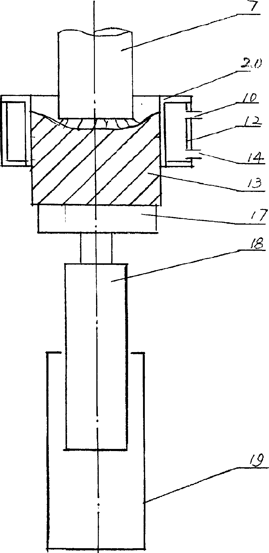
[0045] specific implementation plan

[0046]Basic design idea of ​​the present invention is embodied in the following aspects:

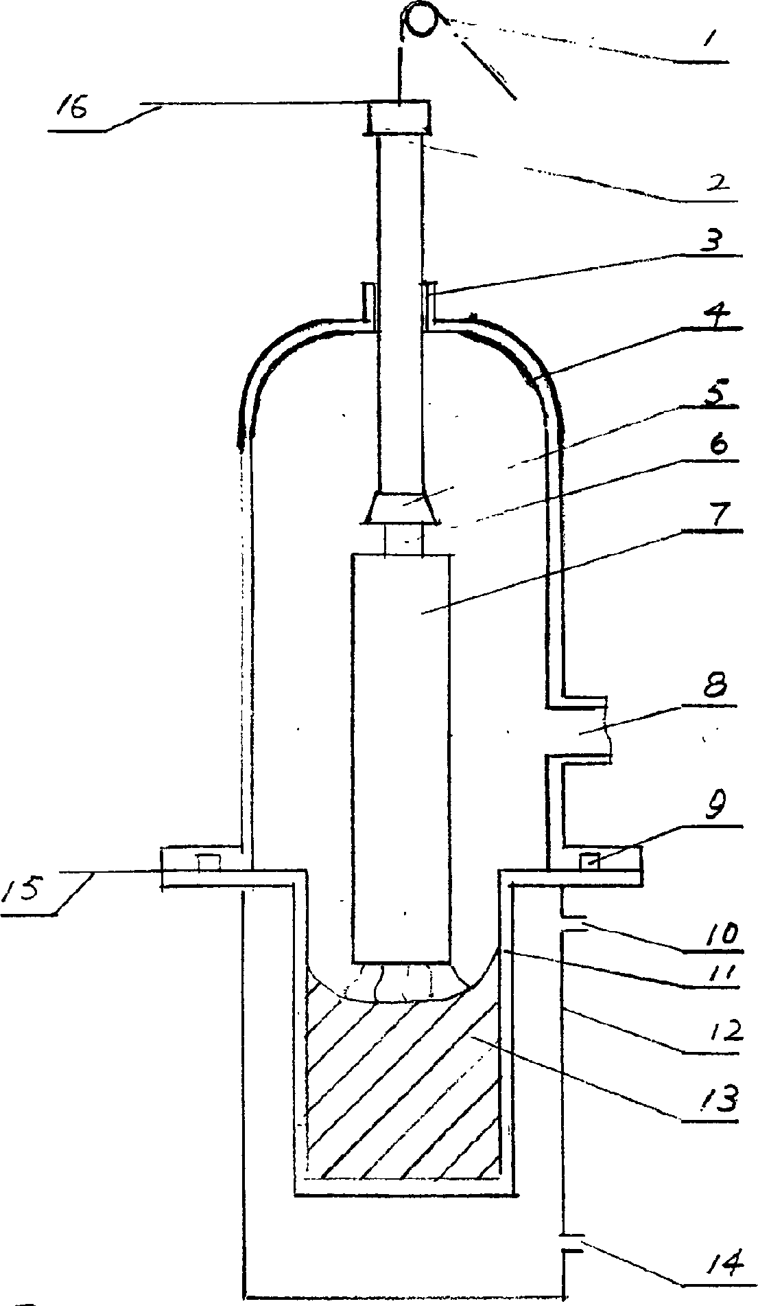
[0047] 1. The present invention adopts the furnace welding electrode technology. When the left manipulator holds one electrode and is smelting in the crystallizer, the right manipulator holds the other electrode for preparation. After the smelted electrode gradually becomes shorter, the right manipulator moves the next electrode to the top of this electrode. , the lower electrode melts normally, the welding power supply is sent between the upper electrode and the lower electrode, and the two electrodes are welded. After the welding is completed, the right clamping hand is supplied with the melting power supply, and the left clamping hand is released, retreated, and rotated out. Continue to grab the next electrode.

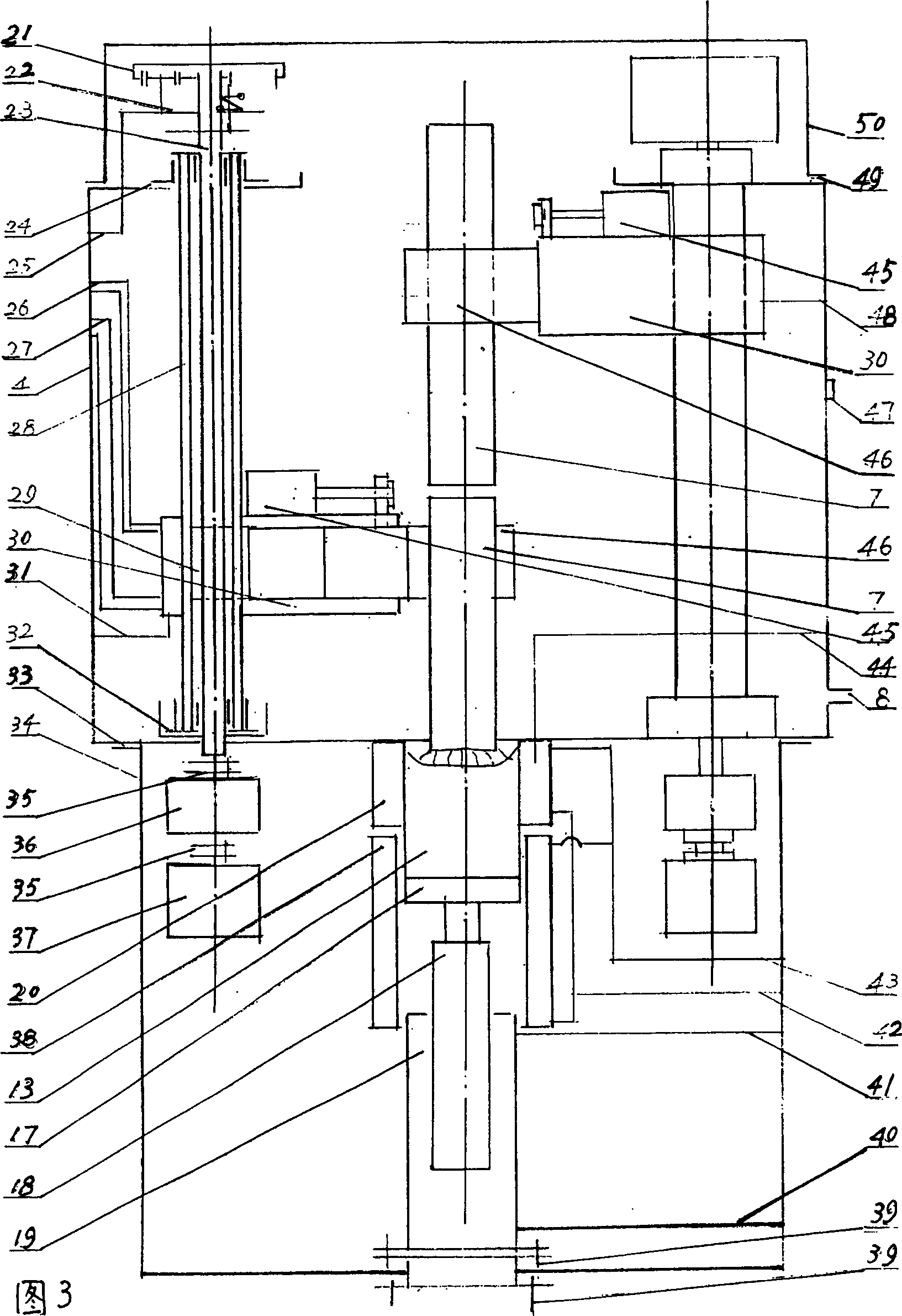
[0048] 2. The present invention adopts two mechanical arms with the same structure in the furnace. The mechanical arms are sleeved on ...


PUM


Abstract

The invention relates the internal furnace electrode automatic welding vacuum consumable furnace, comprising furnace body, double-sleeve upright column, and mechanical arm device, cooler crystallizer at the middle of bottom furnace, wall-cooling surface, dummy head, dummy bar, and dummy actuating device at the bottom of dummy bar. The characters are following: at one end of upright column there is servomotor and harmonic decelerator, which are connected with elevating screw in upright column and lifting screw through coupler, and at the other end of upright column there is planetary deceleration mechanism which is connected with upright column through clutch; the mechanical arm comprises arm, telescopic arm and clamping hand, and the lifting screw drives the arm; the return circuit of melting electrical source comprises dummy head mechanical arm, the welding power source superposes between two mechanical arms; the vacuum system, hydraulic system, voltage control system, cooling system, smelting electrical source, welding power source are installed on out of furnace; the clutch is electromagnetic clutch, when the clutch switches on, the elevating screw drives upright column and drives mechanical arm.

Description

Technical field [0001] The invention relates to special equipment for high-temperature metal vacuum smelting Background technique [0002] Metal materials are the material basis for the survival and development of human beings. In various technical fields, especially high-tech fields, the requirements for metal materials are getting higher and higher, resulting in more and more applications of vacuum melting. At present, developed countries widely adopt vacuum melting technology to produce various steels and non-ferrous metal alloys. [0003] Vacuum melting is a method of melting and purifying metal at high temperature under vacuum. Commonly used vacuum melting methods include: vacuum induction melting, vacuum consumable electrode arc furnace melting, electron beam melting, etc. Various smelting methods have different effects on the properties of smelted alloys. Generally speaking, vacuum consumable electrode arc melting can improve the plasticity of the alloy at high tem...

Claims


Application Information

Patent Timeline
Patent Type & Authority Applications(China)
IPC IPC(8): C22B9/04C22B9/20F27B3/08
Inventor 王晓邦崔中沈嘉麟
Owner 王晓邦
Why Eureka
Try Eureka