
High-speed treating apparatus for organic waste

An organic waste, high-speed treatment technology, applied in biological sludge treatment, aerobic process treatment, chemical/physical process, etc., can solve problems such as increased agitator load, unsmooth air circulation, unbalanced load, etc.

Inactive Publication Date: 2006-10-04
金基台
View PDF0 Cites 14 Cited by
  • Summary
  • Abstract
  • Description
  • Claims
  • Application Information

AI Technical Summary

Problems solved by technology

Even if there is no power failure or failure, after a period of operation, the high-viscosity sludge will accumulate inside the reactor, which will increase the load on the agitator, increase power consumption, and prevent the air entering from the lower side from circulating smoothly, which is not conducive to good performance. Oxygen environment creation
[0008] Moreover, the stirring rotation shaft of most devices in the existing elimination methods only rotates in a single direction, causing more organic waste (microbial regulator + organic (food) waste) in the reactor to accumulate on the stirring rotation shaft The rear of the rotation direction, that is to say, there will be an inclination angle of 30 degrees, which will cause an unbalanced load of the device, and the airtight state of the stirring rotation shaft will easily form cracks due to the continuous thrust (thrust). After the moist gas leaks from the crack, it will cause a strong stench, and the airtight effect of the shaft will gradually decrease after the microbial regulator and grease are mixed and discharged, and finally it will fail to operate.
[0009] The device in the existing elimination method will generate humid gas containing moisture above 40°C when decomposing organic waste, and adopts a heat exchange method based on a refrigerator to separate the gas and moisture, resulting in complex devices, excessive energy consumption, and Disadvantages of low economy

Method used


Image

  • High-speed treating apparatus for organic waste
  • High-speed treating apparatus for organic waste
  • High-speed treating apparatus for organic waste

Examples


Embodiment Construction

[0041] The present invention will be further described below in conjunction with the accompanying drawings.

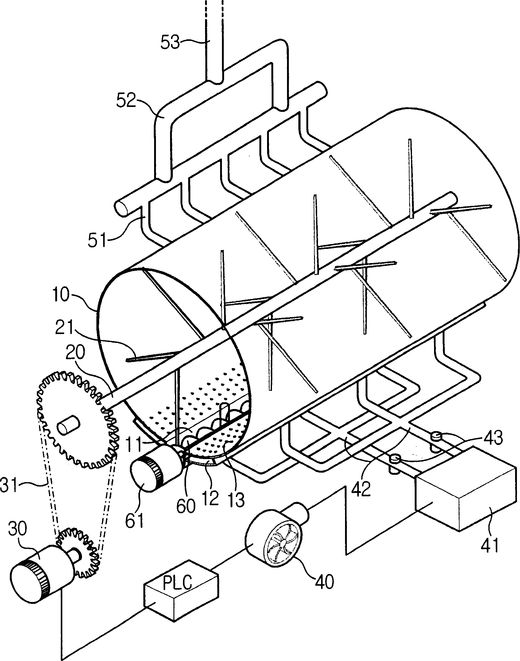
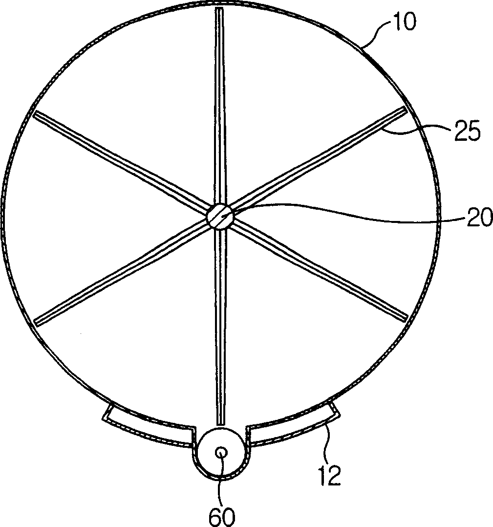
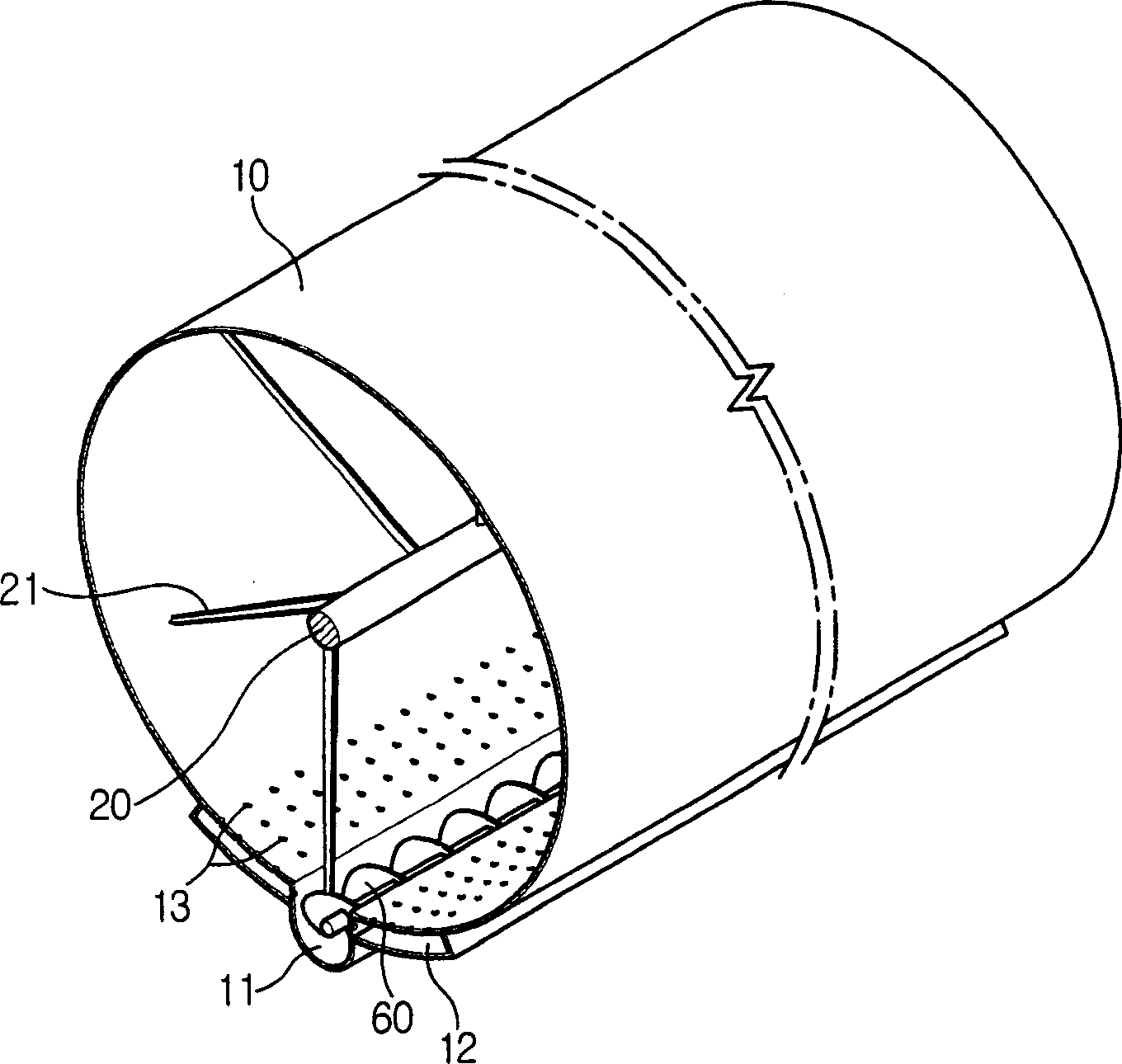
[0042] Figure 1 to Figure 7 It is an explanatory diagram of the high-speed organic waste processing equipment of the present invention.

[0043] As shown in the figure, the present invention comprises: a sealed cylindrical reactor (10); a stirring rotating shaft ( 20); in order to drive the first drive motor (30) connected by the transmission chain (31) in order to drive the stirring rotating shaft (20); there is an internal organic (food) waste that can be disposed on the lower side of the above-mentioned reactor (10). An air supplier (40) for supplying air; the upper side of the above-mentioned reactor (10) has a humid gas processor (50) capable of sucking, treating and discharging the humid gas generated by the internal organic waste. In order not to be affected by the first driving motor (30) when it is forward / reversing and to prevent the leakage of moist gas o...


PUM


Abstract

The present invention provides a high-speed treatment apparatus for organic waste that easily discharges domestic organic waste during the cleaning of the apparatus and water seeping out of the same during a long period of operation stop and safely blocks the inflow of a microorganism controlling agent and sludge to its double jackets. The organic waste treatment apparatus comprises a cylindrical reactor 10 having a feeding port on its upper part, a rotational axis 20 of a stirrer equipped with stirring blades 21, a first driving motor 30 that drives the rotational axis 20 of the stirrer, an air supplier 40 that supplies domestic organic waste with air, and a high-humidity gas treatment device that takes in and treats high-humidity gas coming out of the domestic organic waste. Beneath the circumferential bottom of the cylindrical reactor 10, a screw conveyer casing 11 is attached parallel to its axial direction. A screw conveyor 60 driven by another driving motor is installed in the screw conveyor casing 11. An air jacket 12 having a plurality of air supply holes 13 on its upper surface namely the circumferential wall of the reactor 10 is attached to each side of the screw conveyor casing 11.

Description

【Technical field】 [0001] The present invention provides a High Speed ​​Treatment Machine for Organic Waste, especially one that can provide the best growth environment for microorganisms, and treat the food with aerobic digestion in a short period of time (24 hours). More than 95% of the organic waste mainly garbage, and the organic waste high-speed processing equipment that makes the derivatives of the above-mentioned organic waste lower than the environmental standard value. 【Background technique】 [0002] The organic waste produced in our food culture is mainly food waste and waste produced in slaughterhouses, chicken slaughterhouses, product processing plants and sewage treatment plants. Among these organic (food) wastes, the average daily discharge of food waste in 2002 was as high as 11,397 tons / day, equivalent to 14 trillion won. If the organic (food) waste generated by slaughterhouses and sewage treatment plants is added, it will reach 31,397 tons per day. When the...

Claims


Application Information

Patent Timeline
IPC IPC(8): B09B3/00
CPCY02A50/20B09B3/00C02F3/20C02F11/02B01F27/60
Inventor 金基台罗殷洙
Owner 金基台
Learn More