
Apparatus and method for distance measurement using chaos laser of optical fiber laser device

A fiber laser and chaotic laser technology, which is applied to measurement devices, instruments, radio wave measurement systems, etc., can solve the problems of small measurement distance, low accuracy, and blind spots in distance measurement, and achieve simplified devices, high long-distance and speed resolution capabilities. , The effect of measuring a wide range of distances

Inactive Publication Date: 2006-10-11
TAIYUAN UNIV OF TECH
View PDF0 Cites 23 Cited by
  • Summary
  • Abstract
  • Description
  • Claims
  • Application Information

AI Technical Summary

Problems solved by technology

[0005] The purpose of the present invention is to provide a fiber laser chaotic laser ranging device and method to solve the problem of low precision in direct pulse laser ranging and the existence of blind spots in distance measurement in the prior art, and the measurement distance is relatively large during continuous wave phase laser ranging. Problems that are small and require precision sinusoidal modulation circuits

Method used


Image

  • Apparatus and method for distance measurement using chaos laser of optical fiber laser device
  • Apparatus and method for distance measurement using chaos laser of optical fiber laser device

Examples


Embodiment Construction

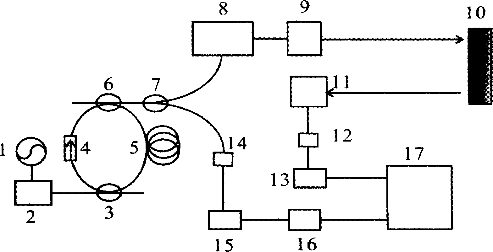
[0016] The chaotic laser signal used for ranging is generated in the fiber laser, which can be modulated by a single-ring fiber laser or generated by using two single-ring fiber lasers to form a double-ring fiber laser. The following is a further explanation by taking a single-ring fiber laser plus modulation to generate chaotic laser for ranging as an example in combination with the attached drawings:

[0017] The chaotic laser signal generating device includes a laser pulse drive power supply 1, a semiconductor laser 2 and a fiber ring composed of a wavelength division multiplexer 3, an optical isolator 4, a doped fiber 5, and a fiber coupler I6. The laser pulse drive power supply 1 provides DC bias and modulation current pulses for the laser; the semiconductor laser 2 is used to pump the doped fiber 5, and different doped fibers can be selected from semiconductor lasers with different wavelengths, such as 980nm for erbium-doped fibers. The quantum well laser; the wavelength...


PUM


Abstract

The invention relates to an optical fiber laser chaos laser ranging device and relative method. It is characterized in that: the chaos optical fiber laser uses the optical fiber laser to generate chaos laser signal, and via the optical fiber coupler II to divide the chaos laser signal into the detecting light I and the reference light II; the detecting light I via the optical fiber amplified is amplified to irradiate the object via the laser collimate system; the reflective wave signal of object is collected by the telescope and transformed into electric signal via the optical electric detector I; then via A / D converter, the analogue signal is transformed into digital signal to be input into computer; the reference light II directly irradiates the optical electric detector II whose properties are same to the optical fiber amplifier, to transform the optical signal into electric signal, then via the A / D converter, to be transmitted to the adjustable electric delay wire to be input into the computer; then attaining the detected distance. The invention uses the chaos laser signal generated by the optical fiber laser to range, uses the cross-correlation character of chaos laser to extract the laser fly time, with high anti-disturb ability, high noise tolerance, high accuracy and wider detecting range.

Description

technical field [0001] The invention belongs to the field of laser ranging methods and devices. In particular, the method and device for realizing precise distance measurement by using a fiber laser to generate chaotic laser signals can be applied to fields such as industrial and agricultural production, military affairs, communication, and remote sensing. Background technique [0002] Laser ranging is one of the preferred solutions for measuring distance. It is a method to realize high-precision distance measurement by using the characteristics of laser monochromaticity, strong coherence and directivity. At present, the Flight-time Measurement Methods are widely used in laser ranging. The principle is to measure the time Δt required for the light signal to travel back and forth from the rangefinder to the target on the survey line, and then calculate the distance D to be measured according to D=c·Δt / 2, where c is the speed of light. From the technical approach, it can be ...

Claims


Application Information

Patent Timeline
IPC IPC(8): G01S17/08
Inventor 王云才杨玲珍贺虎成王冰洁王安帮
Owner TAIYUAN UNIV OF TECH
Learn More