Flyback power converter

A power converter, a flyback technology, applied in the output power conversion device, the conversion of DC power input to DC power output, the conversion of AC power input to DC power output, etc., can solve the problem of high power consumption, flyback power The converter lacks regulation, easily destroys the transistor, etc.

Inactive Publication Date: 2006-10-11
SYST GEN
View PDF1 Cites 4 Cited by
  • Summary
  • Abstract
  • Description
  • Claims
  • Application Information

AI Technical Summary

Problems solved by technology

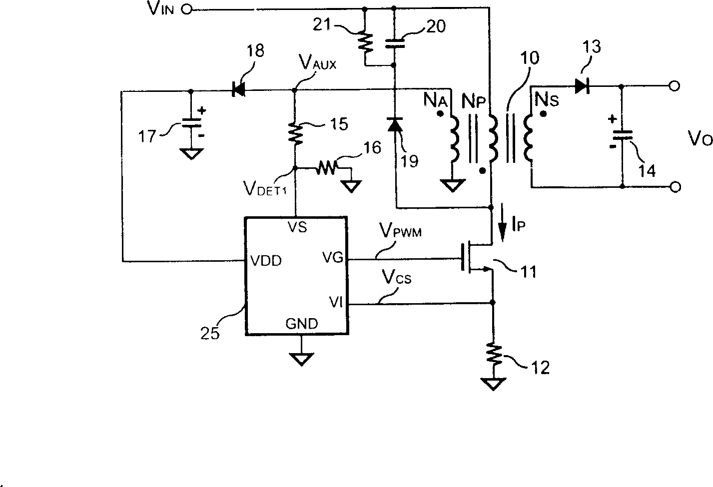
The first disadvantage is that the leakage inductance of the transformer 10 leads to high power consumption. In addition, because the leakage inductance will store energy, it is easy to form a high voltage surge, which is easy to damage the transistor 11. Therefore, the conventional flyback power converter is used to protect the transistor. 11 is provided with a snubber circuit, which includes a snubber diode 19, a snubber capacitor 20 and a snubber resistor 21, which are used to consume the energy stored in the leakage inductance of the transformer 10, avoiding the formation of high voltage surges to protect the transistor 11
[0013] The second disadvantage is the lack of regulation of flyback power converters under light load and no load conditions
If the output load of the flyback power converter is lower than the auxiliary winding N A When the load is high, the energy stored in the transformer 10 will only be able to pass through the diode 18 and the auxiliary winding N A Released to the supply capacitor 17, so when the transistor 11 is cut off, the rectifier 13 will remain in the off state, so the output voltage V of the flyback power converter O not available from the auxiliary winding N A Feedback to the controller 25, so in the light load and no load state, the detection voltage V generated by the voltage detection terminal VS DET1 It is only related to the voltage of the supply terminal VDD, so the conventional flyback power converter lacks adjustment
[0014] Another known technology is the US Patent No. 6,853,563 "Primary-side controlled flyback power converter (Primary-side controlled flyback power converter)" proposed by Mr. Yang et al. One of the main shortcomings of this known technology It is Electromagnetic Interference (Electric and Magnetic Interference, EMI), which is caused by the fact that the drain of the transistor is directly connected to the positive power supply rail, so a parasitic capacitance of the transistor is coupled with a parasitic inductance, thus forming a high-frequency resonance tank , which will generate higher electromagnetic interference

Method used


Image

  • Flyback power converter
  • Flyback power converter
  • Flyback power converter

Examples


Embodiment Construction

[0053] In order to enable the examiner to have a better understanding and understanding of the structural features and achieved effects of the present invention, I would like to provide a diagram of a better embodiment and a detailed description, as follows:

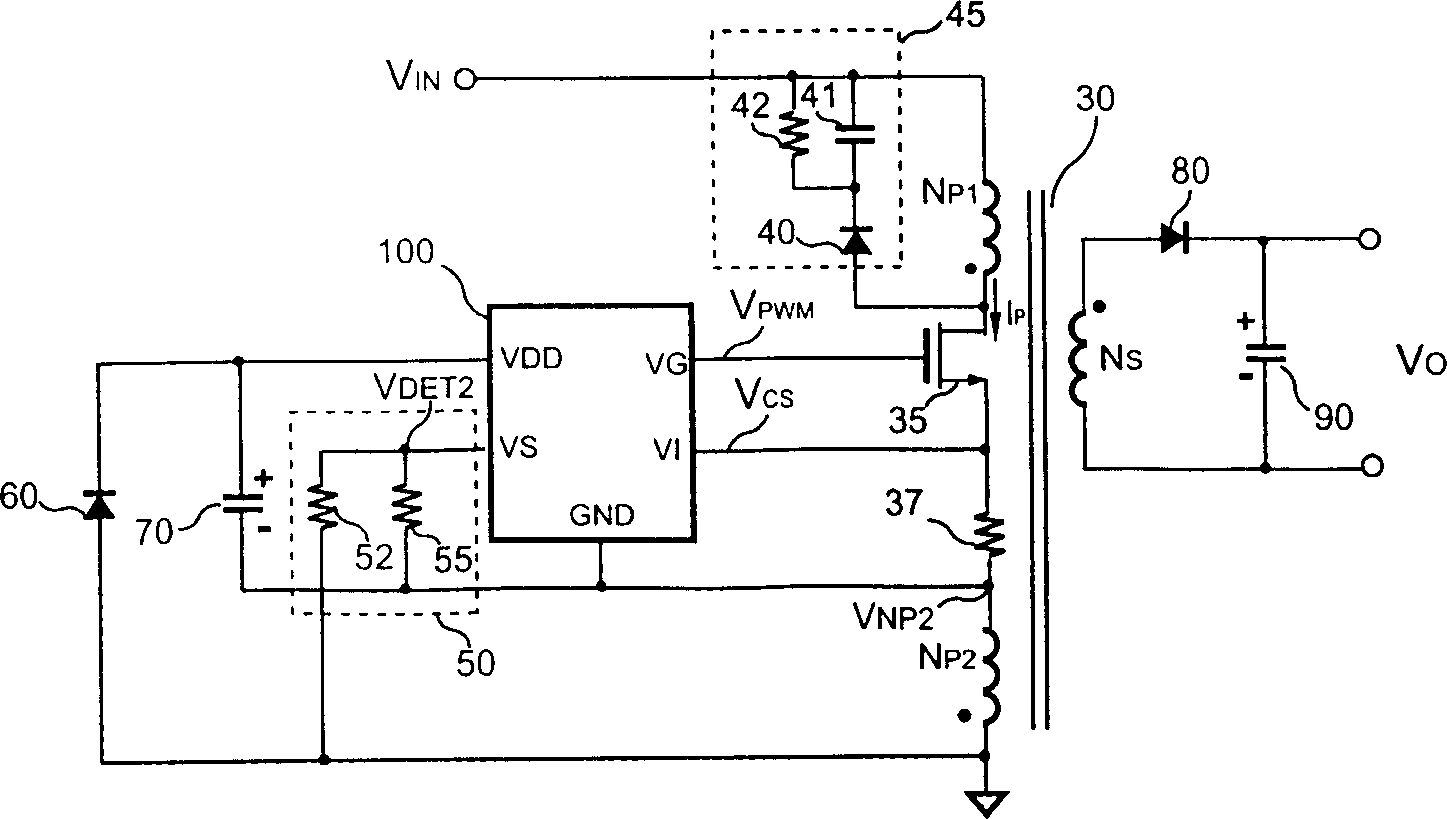
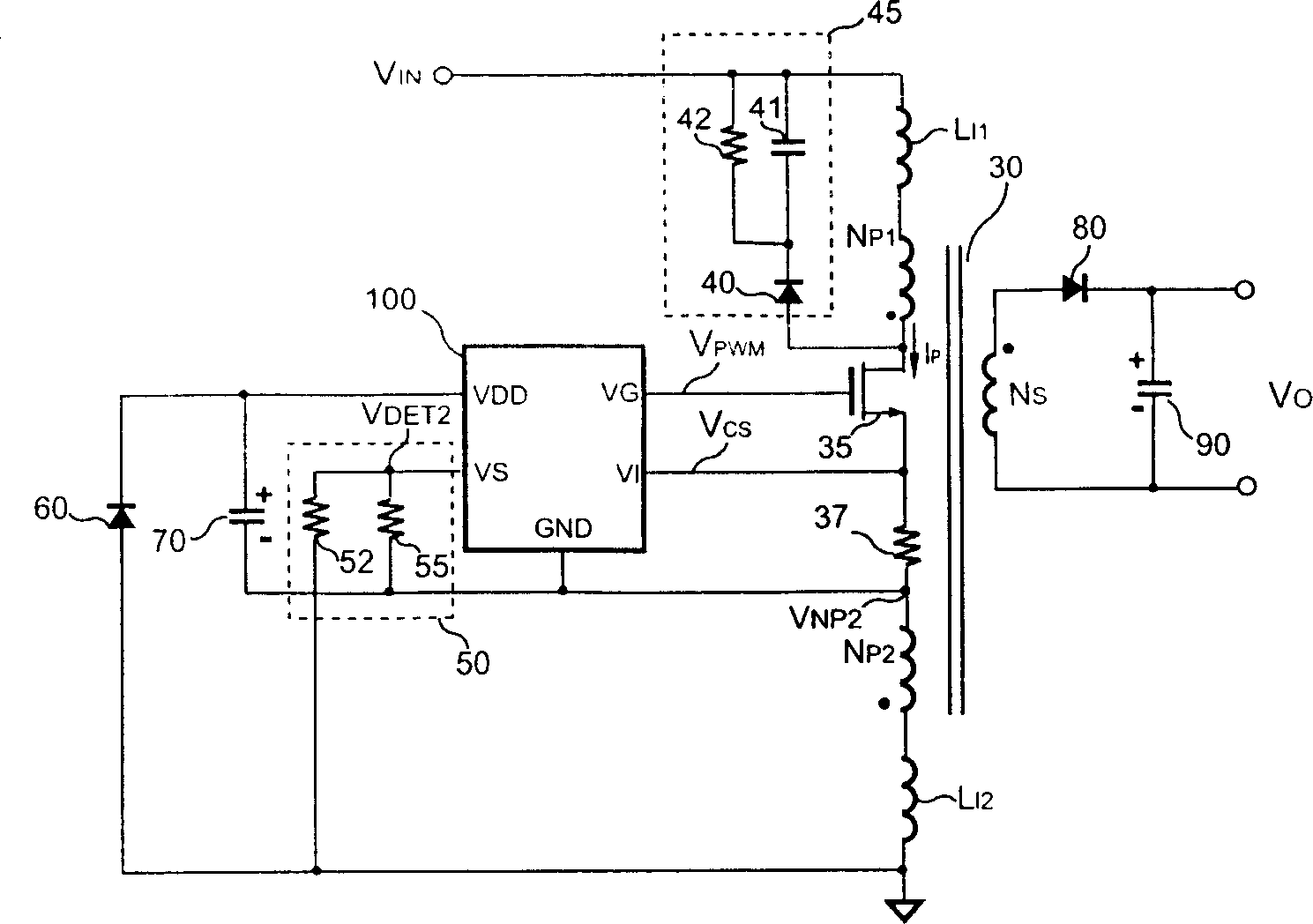
[0054] see figure 2 , is a circuit diagram of a flyback power converter according to a preferred embodiment of the present invention. As shown in the figure, the flyback power converter of the present invention includes a transformer 30 for storing energy and transferring the stored energy from a primary side of the transformer 30 to a secondary side of the transformer 30 . Wherein, the primary side of the transformer 30 is provided with a cut-first primary side winding N P1 with a second primary winding N P2 , and the secondary side of the transformer 30 is provided with a secondary side winding N S . The first primary side winding N P1 with the second primary winding N P2 Coupled to the power supply rail of the ...


PUM


Abstract

The related power converter comprises: a transformer with a first/second primary winding coupled to positive/negative power supply rail, an electric crystal connected between two windings to switch the transformer, a control circuit coupled the crystal with the second winding to produce a switch signal, a supply capacitor coupled with the control circuit to supple power, and a diode coupled the negative rail and capacitor. Wherein, there is a leakage inductance on the second winding to store some energy when crystal on conduction and release the energy to capacitor when crystal cut-off. This invention can improve converter efficiency and reduces EMI.

Description

Technical field: [0001] The present invention relates to a power converter, in particular to a flyback power converter. Background technique: [0002] By the way, power converters have been widely used to provide adjustable voltage and current. At present, the focus of research on power converters is how to make power converters more efficient and save power. The flyback power converter generally includes a controller, a transistor and a transformer. The controller is used to sense the output voltage and / or output current of the flyback power converter and generate a control signal to control the transistor. Switching and adjusting the output voltage and / or output current of the flyback power converter. [0003] see figure 1 , which is a circuit diagram of a conventional flyback power converter. As shown in the figure, the conventional flyback power converter includes a transformer 10, which includes a primary winding N P , primary and secondary side winding N S with an...

Claims


Application Information

Patent Timeline
Patent Type & Authority Applications(China)
IPC IPC(8): H02M3/28H02M3/335H02M7/537
Inventor 杨大勇
Owner SYST GEN
Why Eureka
Try Eureka