
Biological extrusion screw and method for making same

A technology for extruding screws and manufacturing methods, applied in medical science, internal bone synthesis, fastening devices, etc., can solve the problems of strong stress shielding effect, local effusion reaction, cortical bone atrophy and loosening, etc., and achieve good mechanical properties. The effect of strength, easy installation and easy disassembly

Inactive Publication Date: 2006-11-22
湖南恒天生物科技有限责任公司
View PDF1 Cites 5 Cited by
  • Summary
  • Abstract
  • Description
  • Claims
  • Application Information

AI Technical Summary

Problems solved by technology

The extruded screw has the following disadvantages and disadvantages in terms of materials: although the extruded screw made of metal material has high mechanical strength and fatigue resistance, it can meet the needs of orthopedic surgery for fixation, but there are implant erosion, The possibility of complications such as metal allergy and tumor-causing implant materials, especially in terms of biomechanics, because the elastic modulus difference between metal materials and human bones is too large, the stress shielding effect is too strong, and cortical bone atrophy under the metal materials is prone to occur and loose change, leading to treatment failure
Extrusion screws made of high molecular polymers can be absorbed by the human body, but due to the rapid degradation and absorption time, tendons and ligaments will fall off again, resulting in treatment failure. sex cyst
Screws made of allogeneic bone have good biocompatibility and can be absorbed by the human body without secondary surgery to remove them, but the bone source is difficult and may cause human disease transmission
The heterogeneous cortical bone screw has the advantages of the allogeneic bone screw, and the bone source is abundant, so the prospect of popularization and application is broad. Chinese patent 200510031414.1 discloses a "manufacturing method of heterogeneous bone internal fixator", but it does not disclose that it can meet the above internal fixation requirements. The structure of the required extrusion screw and its specific manufacturing method

Method used


Image

  • Biological extrusion screw and method for making same
  • Biological extrusion screw and method for making same
  • Biological extrusion screw and method for making same

Examples


Embodiment 1

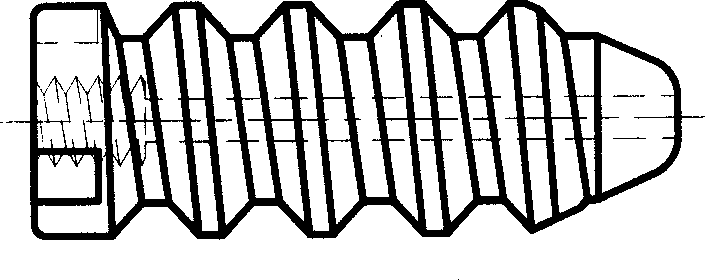
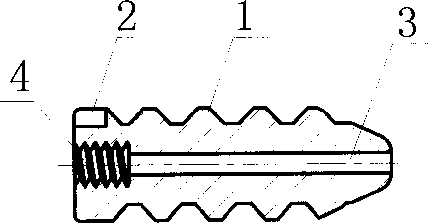
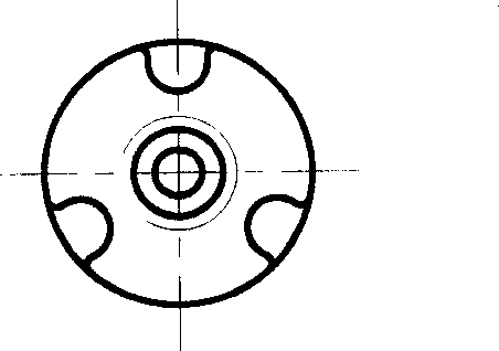
[0027] Embodiment 1: as figure 1 , figure 2 , image 3 As shown, the biological extrusion screw is a cylindrical threaded body 1 with a conical front end. There are three radial grooves 2 evenly distributed in the radial direction on the rear peripheral edge of the cylindrical threaded body 1. The radial grooves 2 are The axial depth is 5 mm, and the root of the groove is a radial notch in the shape of a circular arc. There is a cylindrical through hole 3 in the center of the cylindrical threaded body 1 , and an internal thread 4 is provided at the rear end entrance section of the cylindrical through hole 3 .

[0028]The screw processing method is carried out according to the method disclosed in Chinese patent 200510031414.1, using pigs as raw materials, and the processing steps are carried out in the order of seed selection, slaughter, bone extraction, processing and molding, degreasing, cleaning, packaging, and sterilization. The specific steps are: select pigs that have...

Embodiment 2

[0031] Embodiment 2: as figure 1 , figure 2 , Figure 4 As shown, the biological extrusion screw is a cylindrical threaded body 1 with a conical front end. There are two radial grooves 2 evenly distributed in the radial direction on the rear peripheral edge of the cylindrical threaded body 1. The radial grooves 2 are A radial notch with an axial depth of 6 mm and a square root. There is a cylindrical through hole 3 in the center of the cylindrical threaded body 1 , and an internal thread 4 is provided at the rear end entrance section of the cylindrical through hole 3 .

[0032] The processing method of the screw is carried out according to the method disclosed in Chinese patent 200510031414.1, using sheep as raw material, and the processing steps are carried out in the order of seed selection, slaughter, hanging detoxification, bone extraction, processing and molding, degreasing, cleaning, packaging, and sterilization. The specific steps are as follows: select slaughtered ...

Embodiment 3

[0033] Embodiment 3: as figure 1 , figure 2 , Figure 5 As shown, the biological extrusion screw is a cylindrical threaded body 1 with a conical front end. There are four radial grooves 2 evenly distributed in the radial direction on the peripheral edge of the rear end of the cylindrical threaded body 1. The radial grooves 2 are The axial depth is 4 mm, and the root of the groove is a radial notch in the shape of a circular arc. There is a cylindrical through hole 3 in the center of the cylindrical threaded body 1 , and an internal thread 4 is provided at the rear end entrance section of the cylindrical through hole 3 .

[0034] The processing method of the screw is carried out according to the method disclosed in Chinese patent 200510031414.1, using horses as raw materials, and the processing steps are as follows: selection, slaughter, suspension detoxification, bone extraction, mad cow disease pathogen detection, processing and molding, degreasing, cleaning, packaging, an...


PUM


Abstract

The present invention relates to medical article, and is especially one kind of orthopaedic internal fixer and its making process. The orthopaedic internal fixer is one threaded cylinder with conic front end, two radial slots in the edge of its back end, central axial through hole and inner thread in the back end of the through hole. It may be installed and detached with a special tool easily, and its screw may be machined according to the method of patent No. 200510031414.1. It is made with the bone of ox, horse, sheep, pig or other animal as material and through the steps of taking bone, machining, defatting, cleaning, packing and sterilizing. It can fuse with human body's bone skeleton and may be degraded slowly.

Description

technical field [0001] The invention relates to a medical product and a manufacturing method thereof, in particular to an orthopedic internal fixation device and a manufacturing method thereof. Background technique [0002] At present, orthopedic surgery usually requires the use of internal fixators for fixation. Screws are commonly used internal fixators, such as the fixation method for the treatment of rupture and damage of tendons and ligaments near joints. Usually, tunnels are dug on bones for installation of tendons and ligaments. The ends of the tendons and ligaments are forced to be squeezed around the inner wall of the tunnel with extrusion screws. The screws must be able to fuse with human bone tissue and degrade slowly without adverse side effects. The structure of the extruded screw is generally a cylindrical threaded body with a conical front end, a through hole in the center, and a radial through groove or an inner square groove on the rear end surface, which is...

Claims


Application Information

Patent Timeline
IPC IPC(8): A61B17/86A61L27/00
Inventor 杨守恒陈游
Owner 湖南恒天生物科技有限责任公司
Learn More