Liquid blast furnace slag heat recovering apparatus and method

A technology of heat recovery device and blast furnace slag, which is applied in the direction of heating device, recycling technology, process efficiency improvement, etc., and can solve the problems of liquid slag granulation and high heat recovery efficiency

Inactive Publication Date: 2007-01-03
CHONGQING UNIV
View PDF0 Cites 19 Cited by
  • Summary
  • Abstract
  • Description
  • Claims
  • Application Information

AI Technical Summary

Problems solved by technology

For the heat recovery of liquid blast furnace slag, there are two key issues: one is the granulation of liquid slag; the other is h

Method used


Image

  • Liquid blast furnace slag heat recovering apparatus and method
  • Liquid blast furnace slag heat recovering apparatus and method

Examples


Embodiment Construction

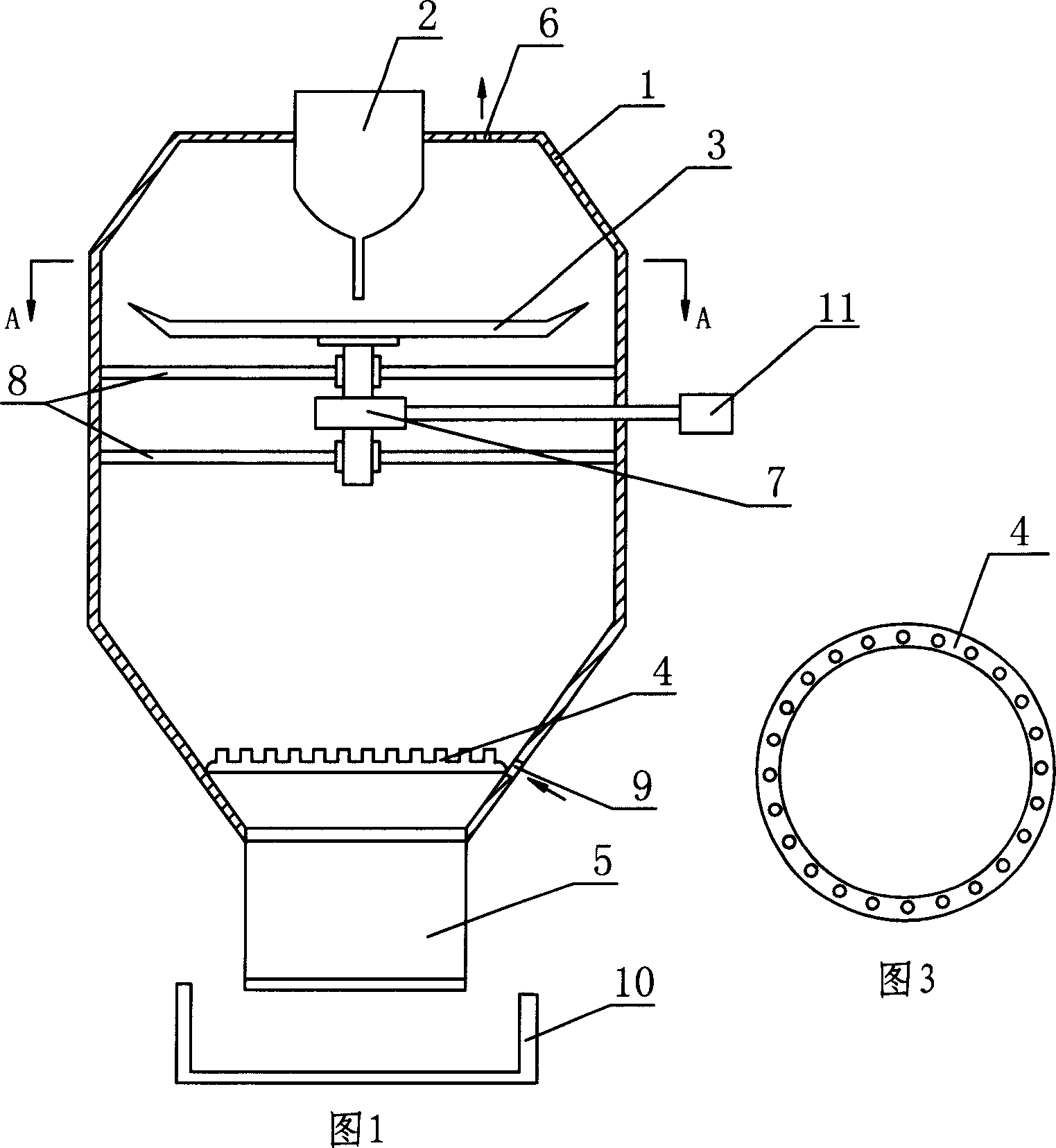
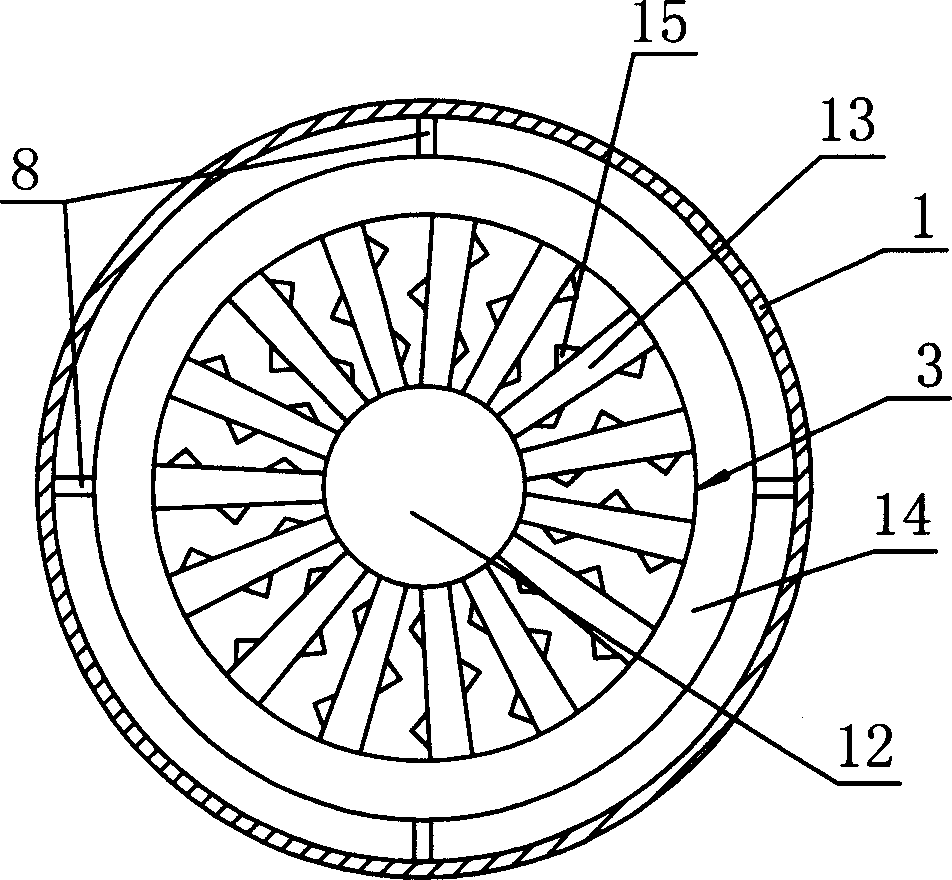
[0031] As shown in Figure 1, the liquid blast furnace slag heat recovery device is mainly composed of a cylindrical airtight container 1, a liquid slag gate 2, a granulation device 3, a cooling gas injection device 4, and a slag sealing and slag cleaning device 5 ;

[0032] The liquid slag gate 2 is set on the top of the cylindrical airtight container 1, and the outer edge of the gate is sealed with the airtight container; in the cylindrical airtight container 1, the lower part of the liquid slag gate 2 is provided with a motor and a transmission system 7. The granulation device 3; the top of the cylindrical airtight container 1 is provided with an air outlet 6, and the lower side wall is provided with an air inlet 9.

[0033] In the figure, 8 is the mounting frame for setting the granulation device 3 and the transmission system 7, 10 is the slag collection tank, and 11 is the motor.

[0034] The granulation device 3 can be a spoke-type granulation device or a cup-type granul...


PUM


Abstract

The liquid blast furnace slag heat recovering apparatus includes one sealed cylindrical container with top gas outlet, one liquid slag gate on the top of the container, one pelletizing unit comprising motor and its driving system inside the container, and one cooling-gas injecting unit. The heat recovering method includes leading liquid blast furnace slag through the gate into the container, pelletizing the liquid slag with the pelletizing unit, heat exchange between the falling blast furnace slag grains and the cooling gas, and exhausting the cooling gas, which is compressed air or nitrogen, after heat exchange through the gas outlet for reuse. The present invention has effective heat exchange.

Description

technical field [0001] The invention relates to energy-saving and secondary energy recovery and utilization technologies in iron and steel metallurgical processes, in particular to a liquid blast furnace slag heat recovery device and method. Background technique [0002] The iron and steel industry is an industry that consumes a lot of energy and resources. In the process of ironmaking, a large amount of heat such as coke is consumed and enters molten iron and steel, coal gas or flue gas, and liquid blast furnace slag. Among them, the proportion of physical heat contained in liquid slag is relatively large. For high-temperature liquid blast furnace slag, due to the high temperature, the accumulated heat is large, and the utilization of its physical heat is one of the most important energy-saving directions for iron and steel enterprises. The full and high value-added utilization of metallurgical secondary resources and energy is one of the keys to the sustainable developme...

Claims


Application Information

Patent Timeline
IPC IPC(8): C21B3/06C21B3/08B02C19/00F24J3/00
CPCC21B2400/026C21B2400/052C21B2400/054C21B2400/068C21B2400/076C21B2400/08Y02P10/20Y02W30/50
Inventor 陈登福刘清才佐祥均邱贵宝温良英董凌燕孙善长白晨光
Owner CHONGQING UNIV
Why Eureka
Try Eureka