Particulate matter-containing exhaust emission controlling filter, exhaust emission controlling method and device

A technology for particulate matter and exhaust gas purification devices, used in exhaust devices, chemical instruments and methods, noise reduction devices, etc., can solve problems such as large ventilation loss, yellow smoke, secondary pollution, etc., to reduce pressure drop, high performance, cost reduction effect

Inactive Publication Date: 2007-01-24
MITSUBISHI HITACHIPOWER SYST LTD
View PDF2 Cites 19 Cited by
  • Summary
  • Abstract
  • Description
  • Claims
  • Application Information

AI Technical Summary

Problems solved by technology

However, these technologies have the following problems in the case of using light oil or heavy oil as fuel for the exhaust gas and in the case of applying these technologies to stationary generators using DE: (i) these filters are based on Fundamentals of PM removal by pore filtration, resulting in large draft losses and often detracting from the performance of high-efficiency DE
(iii) Ashes in the fuel are accumulated in the pores of the filter to cause clogging, which shortens the service life of the filter
(iv) In the case where there is no denitrification device installed downstream of the exhaust gas, NO that is not consumed by burning soot 2 are discharged, resulting in problems such as yellow smoke and secondary pollution

Method used


Image

  • Particulate matter-containing exhaust emission controlling filter, exhaust emission controlling method and device
  • Particulate matter-containing exhaust emission controlling filter, exhaust emission controlling method and device
  • Particulate matter-containing exhaust emission controlling filter, exhaust emission controlling method and device

Examples


example 1

[0068] A stacked block consisting of a 0.2 mm thick perforated corrugated plate and a 0.2 mm thick perforated flat plate is impregnated with a 15% TiO 2 Sol (manufactured by Ishihara Sangyo Co., Ltd.), the plate is made of a nonwoven fabric of silica-alumina fiber (the intersecting corrugated honeycomb is made by NICHIAS Co., corrugated plate pitch: 3.3mm, gap between two flat plates: 1.9mm, external dimensions: 300mm×300mm×300mm), the stacked blocks were air-dried and dried at 150°C. Then, the stacked block was soaked with a dinitrodiammineplatinum solution (Pt concentration: 1.33g / L), dried again and calcined at 600°C to make a substrate for the DPF supporting a 0.2 g / L Pt oxidation catalyst.

example 2

[0070] A substrate for producing a DPF with an oxidation catalyst was produced in the same manner as in Example 1 except that the concentration of dinitrodiammine platinum was changed from 1.33 g / L in Example 1 to 0.32 g / L.

example 3

[0072] By suspending 300 g of TiO in a solution of dinitrodiammine platinum (Pt concentration: 1.7 g / L) 2 Powder (trade name: G5, manufactured by Millennium Pharmaceuticals Co., Ltd., surface area: 320m 2 / g) A slurry prepared was kept at 80°C for 2 hours to allow the Pt component to be absorbed into the TiO 2 s surface. 1 kg of silica gel (trade name: Silicasol-OS, manufactured by Nissan Chemical Industries (Chemical Industry) Co., Ltd., SiO 2 concentration: 20%) was added to 1 kg of the resulting solution, and the pH of the solution was adjusted with a nitric acid solution to obtain a catalyst slurry to be supported in the channel a.

[0073] Prepare a 0.2 mm thick cross-corrugated honeycomb made of a non-woven fabric of silica-alumina fibers (manufactured by NICHIAS Corporation, corrugated plate pitch: 3.3 mm, gap between two flat plates: 1.9 mm, external dimensions : 300mm×300mm×300mm). A method is employed in which the slurry is extracted from Figure 4 Direction A i...


PUM


Abstract

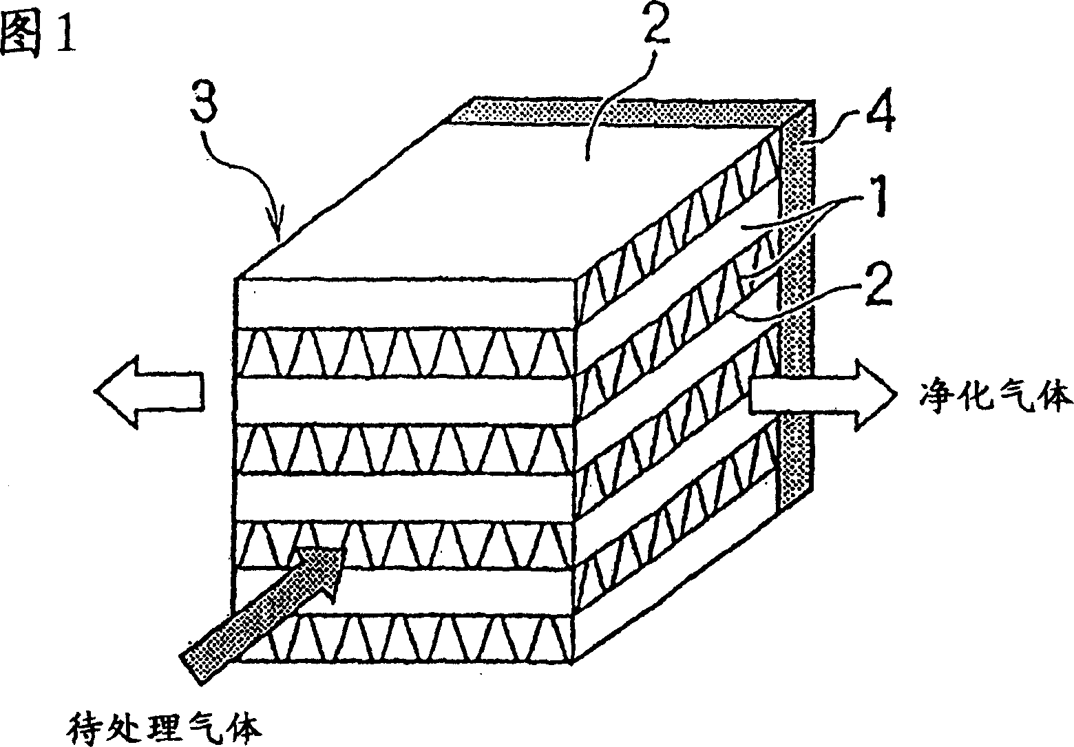
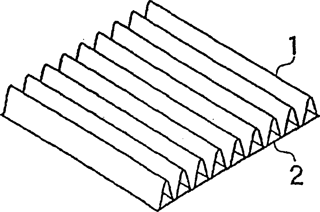
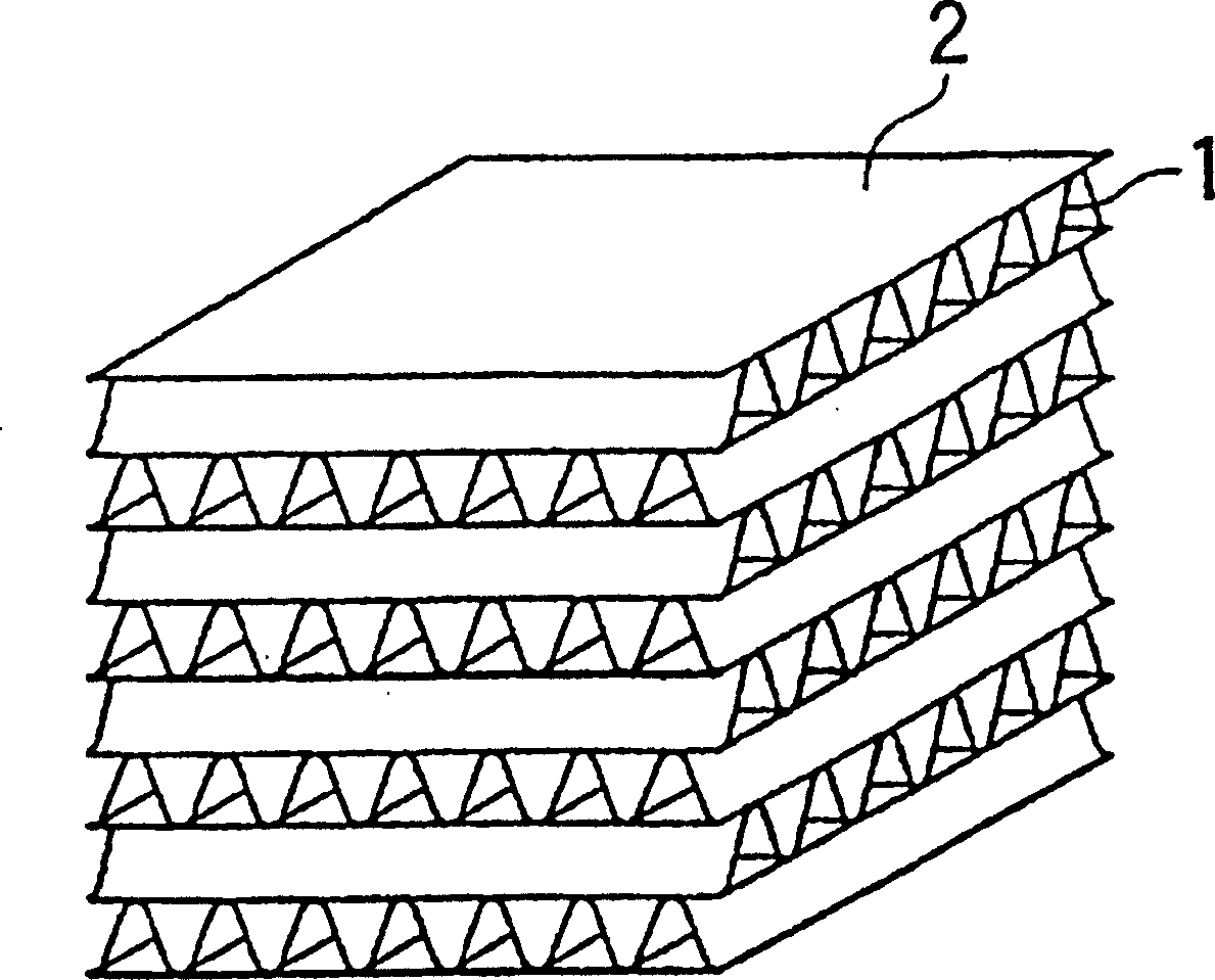
A particulate matter-removing filter being resistant to clogging and ash blocking, requiring no special means such as back-washing and heating combustion, and being formed of inexpensive materials; and exhaust emission controlling method and device using this. (1) A particulate-matter-containing exhaust emission controlling filter which uses as a basic unit a pair of porous corrugated sheet and a porous flat sheet that support an exhaust emission controlling catalyst, has a molding formed by laminating the porous corrugated sheets so that their ridge lines alternately cross perpendicularly, has one of side surfaces, perpendicularly crossing the corrugated sheet ridge lines, of the molding or mutually-adjoining two surfaces that are the perpendicularly-crossing side surfaces sealed, and has exhaust gas in-flow passage and out-flow passage respectively formed between porous corrugated sheets via a porous flat sheet. (2) A filter having the exhaust emission controlling catalyst that is an oxidizing catalyst for oxidizing nitrogen monoxide in an exhaust gas.

Description

technical field [0001] The present invention relates to a particulate matter-containing exhaust emission control filter capable of removing particulate matter (PM) contained in exhaust gases, in particular from diesel engine emissions, in an efficient manner, with low draft losses, and When ash and soot accumulate, the deposits can be removed without employing large-sized equipment; the present invention also relates to a method for purifying exhaust gas containing PM and an apparatus using the above-mentioned filter. Background technique [0002] Diesel engine (DE) is one of the most efficient internal combustion engines because its carbon dioxide (CO 2 ) emissions are reduced and economical, enabling the use of lower quality fuels such as heavy oil. There is a tendency to frequently use diesel engines to prevent global warming. This is due to the reconsideration that automobiles and stationary generators using diesel engines are highly energy efficient and that carbon di...

Claims


Application Information

Patent Timeline
IPC IPC(8): F01N3/02F01N3/24B01D53/92B01J35/04
Inventor 加藤泰良道本孝司宫本英治今田尚美藤泽雅敏小林和树石坂浩广田健
Owner MITSUBISHI HITACHIPOWER SYST LTD
Why Eureka
Try Eureka