

Heating element and production method thereof
A manufacturing method and a heating element technology, which can be used in chemical instruments and methods, electric heating devices, heating element materials, etc., and can solve problems such as insufficient bonding strength
- Summary
- Abstract
- Description
- Claims
- Application Information
AI Technical Summary
Problems solved by technology
Method used
Image

Examples
Embodiment approach 1
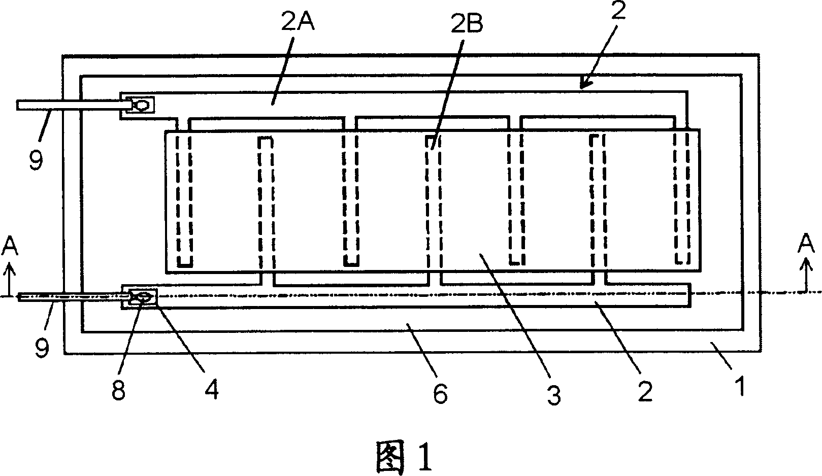
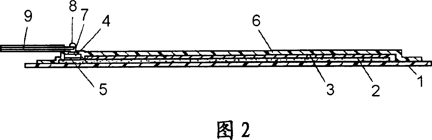
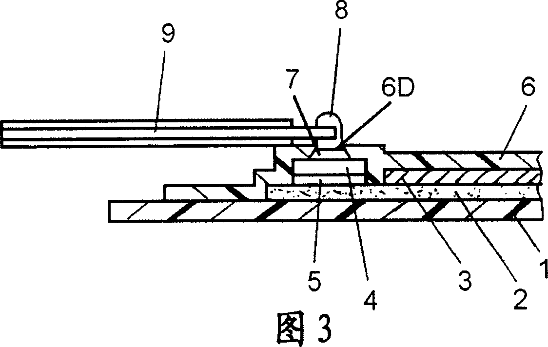
[0029] 1 is a plan view showing the structure of a heat generating body according to Embodiment 1 of the present invention, FIG. 2 is a cross-sectional view of the heat generating body shown in FIG. 1 along line A-A, and FIG. 3 is a main part of the heat generating body shown in FIG. 1 Zoom in on the section view.
[0030] The substrate 1 is made of, for example, a polyethylene terephthalate film with a thickness of 188 μm. A pair of electrodes 2 are provided on the substrate 1 by printing and drying a conductive silver paste. The conductive silver paste constituting the electrode 2 is produced by dispersing silver powder as a conductivity-imparting material in a copolyester resin, and adding an appropriate amount of isocyanate as a curing agent. That is, the electrode 2 contains a resin and conductive powder dispersed therein. The electrode 2 is composed of a main electrode 2A and branch electrodes 2B branched from the main electrode 2A, and the branch electrodes 2B of the ...
Embodiment approach 2
[0068]Fig. 10 is a plan view showing a heat generating body according to Embodiment 2 of the present invention. In this embodiment, the base material 1C has the first reinforcement layer 1A and the first resin layer 1B, and the exterior material 6C has the second reinforcement layer 6A and the second resin layer 6B. The structure of the power feeding part of the electrode 2 is the same as that of the first embodiment.
[0069] Reinforcing layer 1A is a non-woven fabric interwoven with polyethylene terephthalate fibers as a polyester material and long fibers of polyethylene terephthalate as the first fiber are arranged in a specific direction. Reinforcing layer made of laminated non-woven fabrics. The long fibers have high tensile strength and can limit stretchability in the direction in which they are arranged. Also, because of its high bulk density, it does not exhibit the physical properties of a cushioning material. On the other hand, the non-woven fabric layer formed by...
Embodiment approach 3
[0091] The heating element of this embodiment has the same structure as that of FIG. 10 , but the structure of the substrate 1C and the material of the electrodes 2 are different. That is, in such a manner that the thermoplastic polyurethane-based elastomer forming the resin layer 1B is impregnated on the surface of the nonwoven fabric in which polyethylene terephthalate fibers are interwoven to form the reinforcing layer 1A, it is heated at a high temperature. The substrate 1C is formed by lamination by pressing. In addition, the reinforcing layer 1A also contains the same long fibers as in the second embodiment. In addition, the electrodes 2 are formed using a copolyester resin-based conductive paste that is more excellent in flexibility.
[0092] In Embodiment 2, if a conductive paste obtained by dispersing silver powder as a conductivity-imparting agent in a copolyester resin and adding a solvent to adjust the viscosity is used, the flexibility of the electrode 2 can be e...
PUM
| Property | Measurement | Unit |
|---|---|---|
| melting point | aaaaa | aaaaa |
| thickness | aaaaa | aaaaa |
| melting point | aaaaa | aaaaa |
Abstract
Description
Claims
Application Information