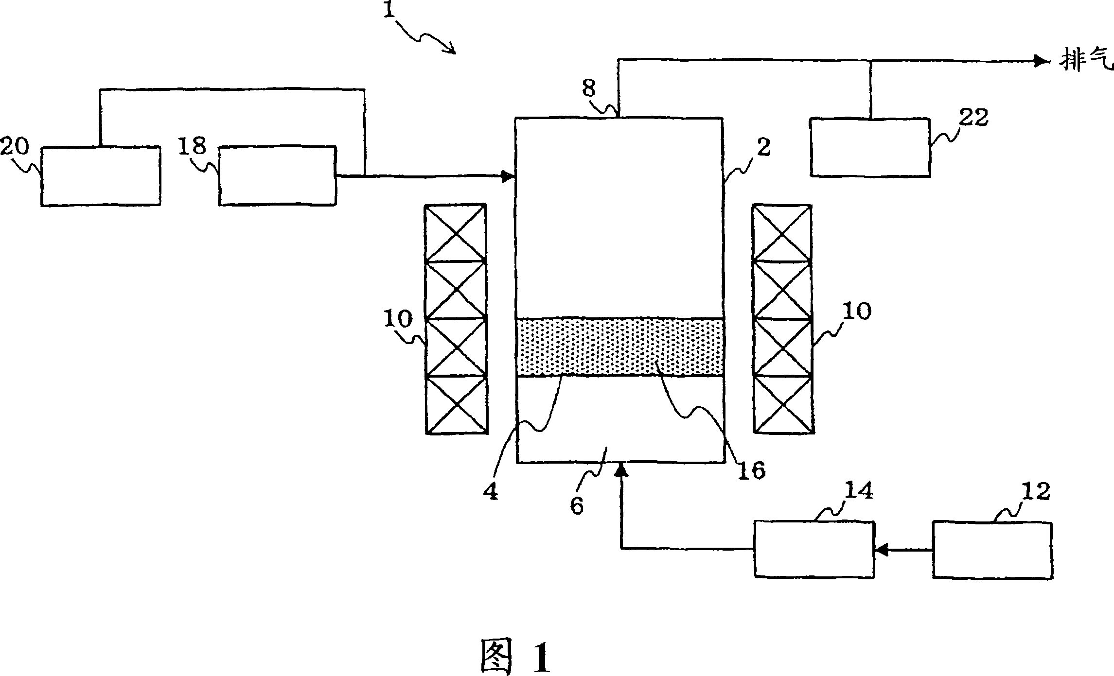
Method for removing tar in fluidized layer furnace

A fluidized bed furnace and tar technology, applied in chemical instruments and methods, cracking, coking ovens, etc., can solve the problems of reduced cooling efficiency, lack of economy, and reduced cracking effect, and achieve high cooling efficiency

Inactive Publication Date: 2007-03-21
IDEMITSU KOSAN CO LTD
View PDF0 Cites 2 Cited by
  • Summary
  • Abstract
  • Description
  • Claims
  • Application Information

AI Technical Summary

Problems solved by technology

[0004] However, in the method (1), the air-conditioning efficiency decreases and the energy loss increases; in the method (2), nickel-molybdenum used as a cracking catalyst component is impregnated in particles such as alumina, the price is high, and the particle fluidization causes Attrition is easy to pulverize, resulting in scattering from the gasifier to the outside of the system, or the carbon components precipitated on the surface of the particles cause a decrease in the cracking effect, so the particles must be replenished, which is not economical; method (3), although high-priced crack

Method used


Image

  • Method for removing tar in fluidized layer furnace

Examples


Embodiment 1~9、 comparative example 1~6

[0060] The calculated tar removal rate per gasification temperature when the above pellets A to E were used. The results are shown in Table 1.

[0061] It should be noted that the tar removal rate was obtained from the following formula, where a represents the amount of tar generated when sand (JIS No. 7) having no tar removal effect is used as the pellets, and b represents the amount of tar generated when each pellet is used .

[0062] Tar removal rate=[1-(b / a)]×100(%)

[0063] particles

[0064] [Powdering rate]

Embodiment 10、11, comparative example 7、8

[0066] The pulverization rate when the above-mentioned Granules A, Granules B, Granules D, and Granules E were used as the granules was determined. The results are shown in Table 2.

[0067] It should be noted that the pulverization rate is obtained from the following formula, d represents the fluidized bed temperature is 800 ° C, the initial particle filling height is 150 mm, and only the raw material is put into the test under the conditions of the gasification time of 1 hour. The weight of residual particles, e represents the initial weight of particles filled.

[0068] Pulverization rate={1-[d / e]}×100(%)

[0069] particles


PUM


Abstract

A method for removing tar in a fluidized layer furnace which comprises subjecting, in a system wherein a raw material is gasified, pyrolyzed or partially oxidized to form an objective gas, a tar formed from the raw material to the adsorption and decomposition by the use of a fluidized cracking catalyst, a fluidized cracking equilibrium catalyst, silica-alumina based particles or alumina based particles prepared by the oil immersion granulation method, and/or to the attachment to a fluidized cracking catalyst, a fluidized cracking equilibrium catalyst, silica-alumina based particles or alumina based particles prepared by the oil immersion granulation method and to burning.

Description

technical field [0001] The present invention relates to a preferred tar removal method in a fluidized bed furnace in a system that gasifies fossil fuels such as coal and heavy oil, biomass, etc. to generate gas for fuel and gas for chemical raw materials. Background technique [0002] Coal gasifiers can be roughly classified into three types: spouted-bed gasifiers, fluidized-bed gasifiers, and fixed-bed gasifiers. Among them, the fluidized bed coal gasifier uses coarse pulverized coal with an average particle size of 1-6 mm. In this way, oxygen or air as a gasification agent fluidizes pulverized coal in it by water vapor, and the conversion of CO to CO is carried out in its furnace. 2 , CO, H 2 conversion. In coal gasification using a fluidized bed, if the reaction temperature is lowered, tar is generated, and operational troubles may occur in the treatment process. Therefore, in the conventional technology, it is operated under the condition that the gasification temper...

Claims


Application Information

Patent Timeline
IPC IPC(8): C10J3/00C10J3/46C10K1/26C10K1/30C10K1/32C01B3/02B01J21/12B01J37/00C10B47/24C10B53/02C10G9/12C10G11/18C10J3/84
CPCB01J37/0072C10G11/18C10J3/84C10K3/023Y02E20/18C10G9/12B01J21/12Y02E50/14C10B47/24C10J2300/1246C10J3/00C10B53/02Y02E50/10Y02P20/52
Inventor 藤原尚树寺前刚宝田恭之守富宽清水忠明
Owner IDEMITSU KOSAN CO LTD
Why Eureka
Try Eureka