Purifying robot

A technology for purifying robots and machine bases. It is applied in the direction of manipulators, claw arms, and manufacturing tools. It can solve the problems of limited range of motion and working space, and achieve the effect of simple and novel mechanism, easy production and maintenance, and large working space.

Inactive Publication Date: 2007-03-28
DALIAN UNIV OF TECH
View PDF3 Cites 15 Cited by
  • Summary
  • Abstract
  • Description
  • Claims
  • Application Information

AI Technical Summary

Problems solved by technology

Since the robot is limited to two-dimensional movement, its range of motion and working space are limited

Method used


Image

  • Purifying robot
  • Purifying robot
  • Purifying robot

Examples


Embodiment Construction

[0030] The present invention is described in more detail below in conjunction with accompanying drawing:

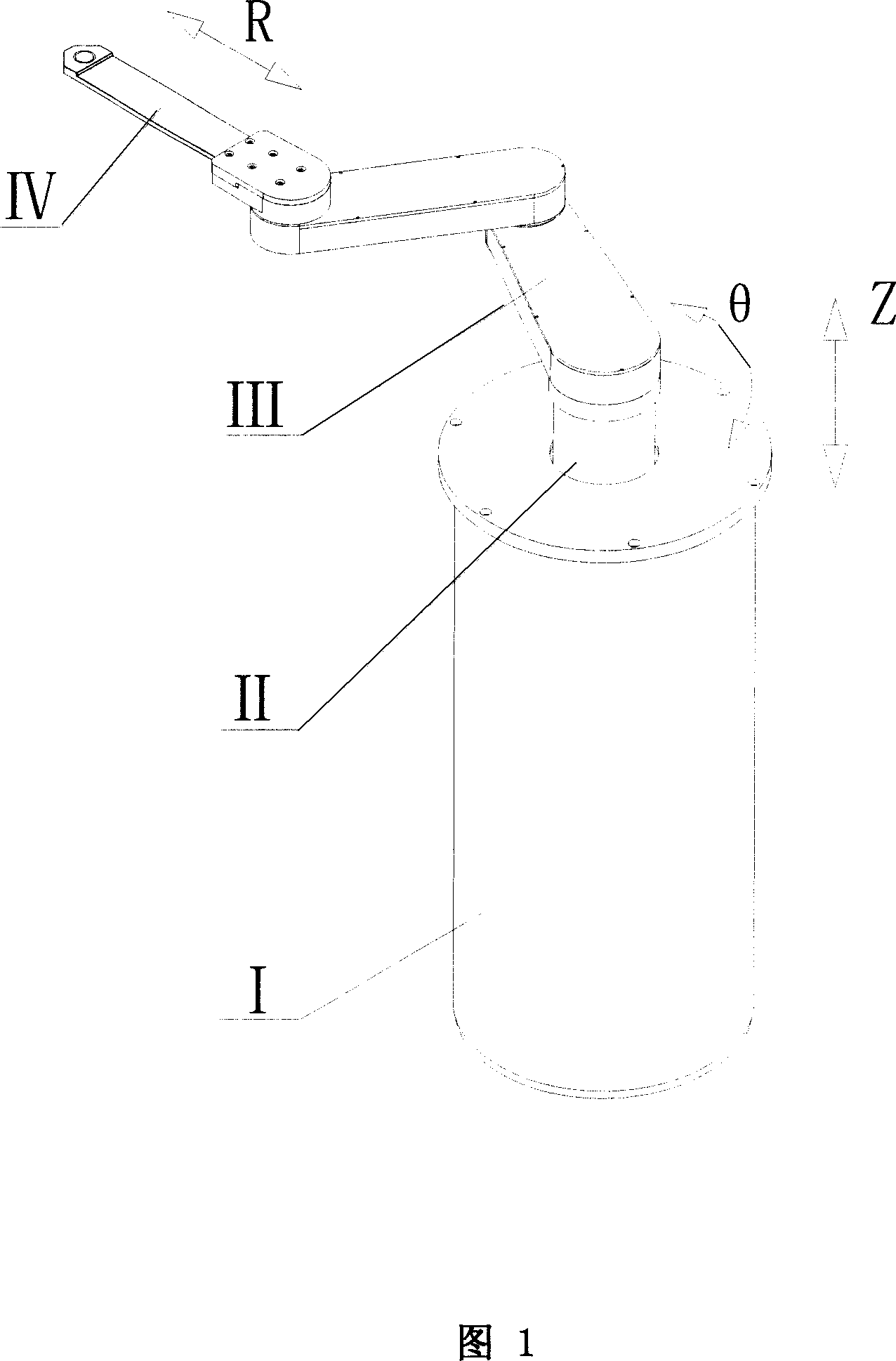
[0031] The cleaning robot of the present invention is composed of a base I, an R-direction linear expansion mechanism III, a θ-direction rotation mechanism II, a Z-direction lifting mechanism II and an end effector IV.

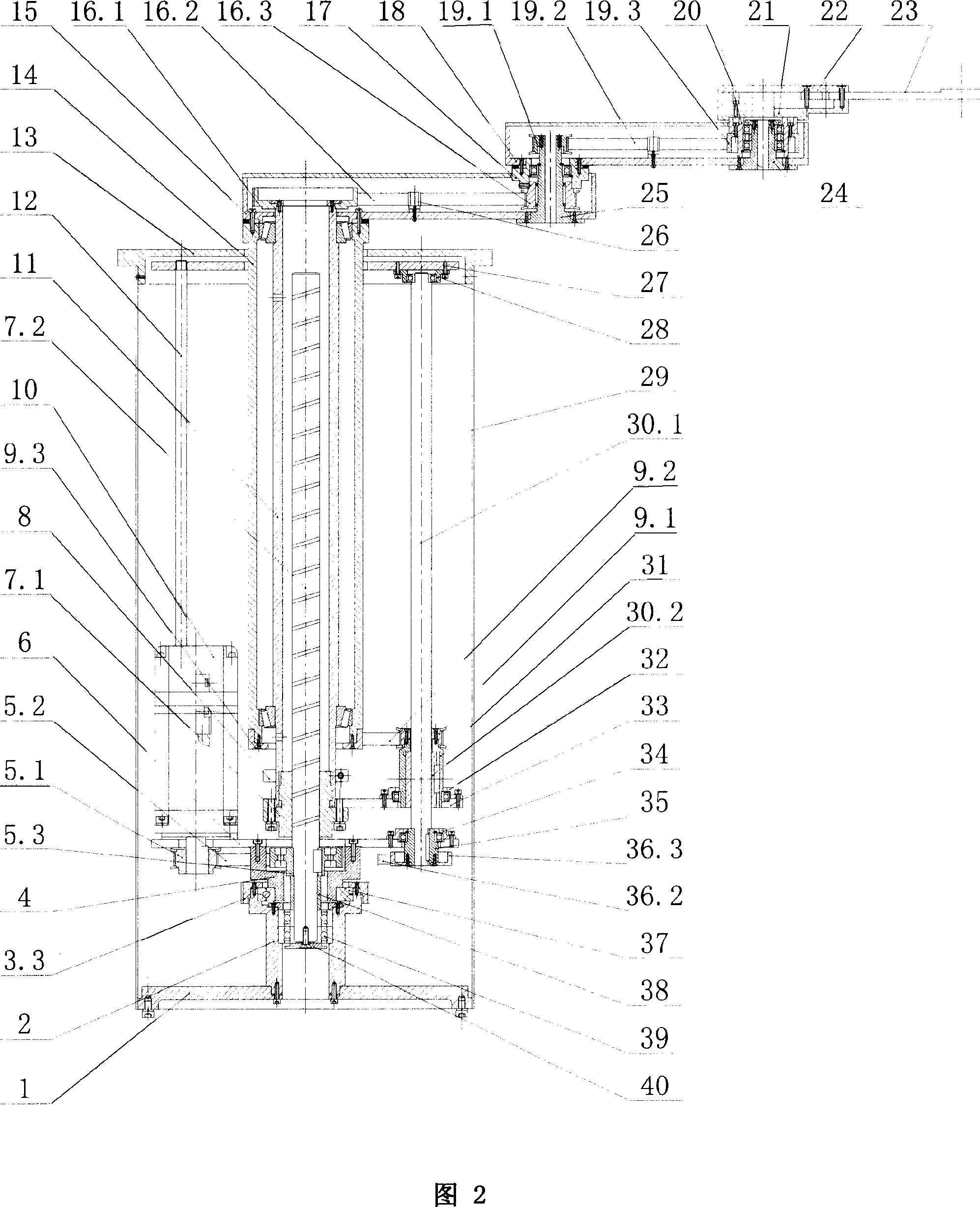
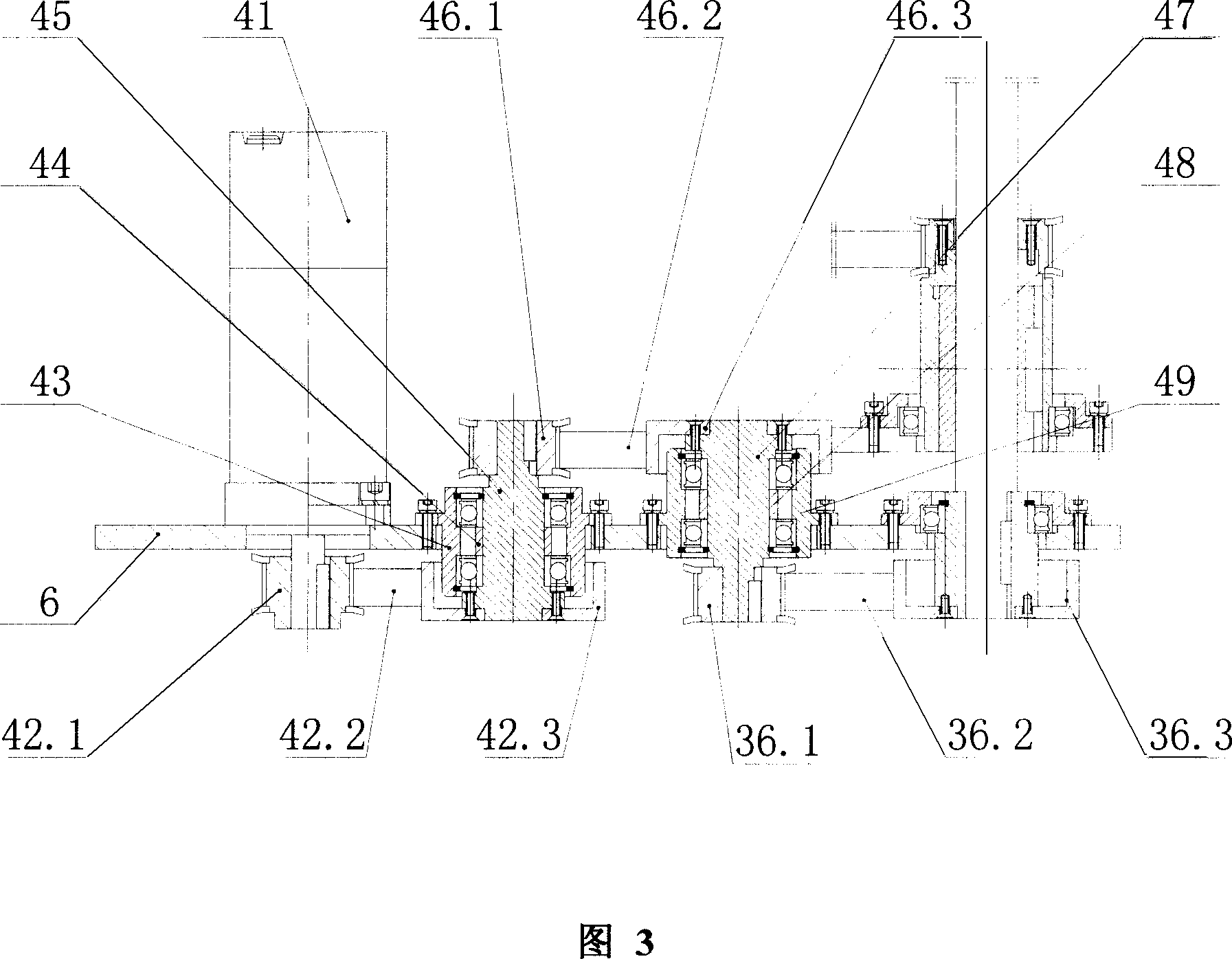
[0032] R-direction movement: the rotating motor 41 drives the ball spline shaft 30.1 to rotate through 3 groups (42.1, 42.2, 42.3; 46.1, 46.2, 46.3; 36.1, 36.2, 36.3) synchronous toothed belt wheel reduction mechanism and the spline bushing 35, The ball spline shaft 30.1 transmits torque through the spline nut 30.2, and then the spline nut 30.2 drives the small synchronous toothed pulley 9.1 connected to it to rotate through the nut jacket 31, and the synchronous toothed belt 9.2 and the large synchronous toothed pulley 9.3 Further drive the outer sleeve 15 and the large arm body 15 fixedly connected with it to rotate around the central axis of the base. T...


PUM


Abstract

The present invention relates to an industrial robot, in the concrete, it is a cleaning robot which is used for implementing chip transmission between different working modules in the integrated circuit production process. It is characterized by that it includes a machine seat, R-direction linear telescopic mechanism, theta-direction rotating mechanism, Z-direction lifting and falling mechanism and tail end executor. Besides, said invention also provides its working principle and concrete operation method.

Description

technical field [0001] The invention belongs to the technical field of industrial robots, and relates to a purification robot, in particular to a silicon wafer transmission purification robot, which mainly refers to a purification robot that realizes silicon wafer transmission between different processing modules in integrated circuit manufacturing. Background technique [0002] The development of microelectronics technology makes integrated circuit manufacturing technology and its equipment always in constant change. Especially at present, with the increase of silicon chip size and the decrease of characteristic line width, higher requirements are put forward for the speed, precision and cleanliness of integrated circuit manufacturing equipment. Silicon wafer transfer system is an essential part in the manufacture of integrated circuits, and cleaning robots play an important role in this system. It is mainly responsible for the precise positioning and fast and smooth handl...

Claims


Application Information

Patent Timeline
Patent Type & Authority Applications(China)
IPC IPC(8): B25J1/04B25J18/04
Inventor 丛明沈宝宏于旭杜宇金立刚
Owner DALIAN UNIV OF TECH
Why Eureka
Try Eureka