Steel wire one-line luminosity modified treatment method and production line

A quenching and tempering treatment and production line technology, applied in heat treatment furnaces, heat treatment equipment, heat treatment process control and other directions, can solve problems such as poor stability, complex process, workpiece distortion, etc., achieve uniform performance and structure, overcome internal and external unevenness, performance and tissue stabilization

Active Publication Date: 2007-03-28
大连环新新材料科技有限公司
View PDF0 Cites 12 Cited by
  • Summary
  • Abstract
  • Description
  • Claims
  • Application Information

AI Technical Summary

Problems solved by technology

[0002] Quenching and tempering treatment is one of the methods with a long history to increase the hardness of metal materials. For wire product steel wire or steel strip (also called forming steel wire), the existing quenching and tempering methods are divided into two types: one method is the wire Quenching and tempering treatment is done above, that is, the whole bundle of wire rods is placed in a periodic furnace, and then quenched and tempered separately, and each treatment process is discontinuous. The biggest disadvantage of this treatment method is that the structure and properties of the treated material are not It is uneven, and the surface oxidation and decarburization are also very serious
Because the user needs a straight product, the whole bundle of wire products needs to be straightened repeatedly with special

Method used


Image

  • Steel wire one-line luminosity modified treatment method and production line

Examples


Embodiment 1

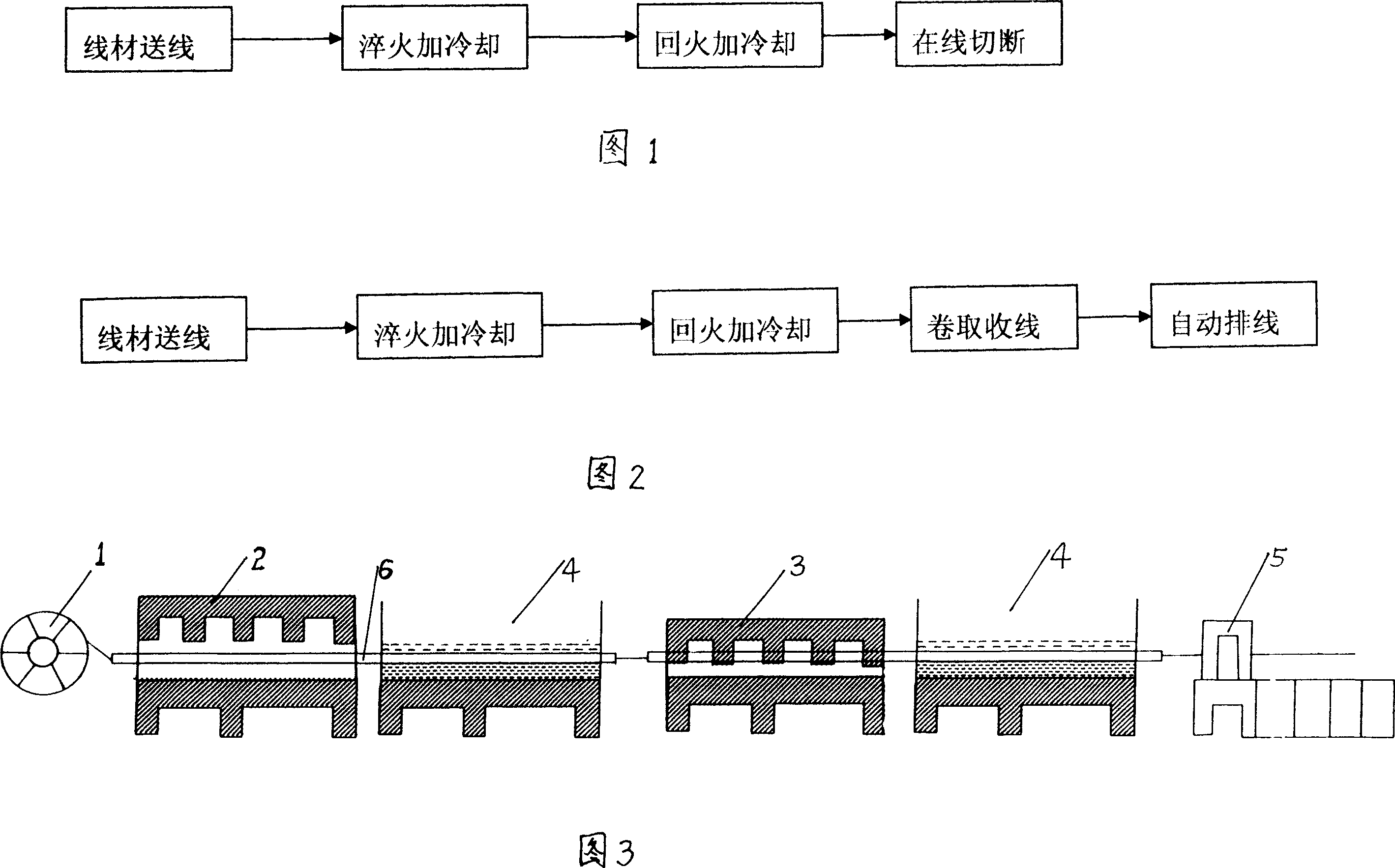
[0021] As shown in Figure 1, the steel quenching and tempering process for molds: the steel wire is released through the pay-off frame, and the linear continuous routing is first quenched through the quenching furnace. The quenching temperature is 1100 ° C, and the quenching cooling temperature is 40 ° C. The wire is tempered through a tempering furnace, the tempering temperature is 650°C, the tempering cooling temperature is 20°C, and then the material is discharged and cut into the required length on the wire. Both quenching and tempering are carried out under nitrogen atmosphere.

Embodiment 2

[0023] As shown in Figure 1, the steel quenching and tempering process for miniature shafts: the steel wire is released through the pay-off frame, and the linear continuous line is first quenched through the quenching furnace. The quenching temperature is 1070 ° C, and the quenching cooling temperature is 45 ° C. The wires are tempered through a tempering furnace, the tempering temperature is 600°C, the tempering cooling temperature is 25°C, and then the material is discharged and cut into required lengths online. Both quenching and tempering are carried out under nitrogen atmosphere.

Embodiment 3

[0025] The quenching and tempering treatment process of piston ring wire material as shown in Figure 2: the steel wire is released through the pay-off frame, and the linear continuous wire is first quenched through the quenching furnace. The quenching temperature is 1100 ° C, and the quenching cooling temperature is 48 ° C. The wire is tempered through the tempering furnace, the tempering temperature is 630°C, the tempering cooling temperature is 28°C, and then the material is discharged, and the wire is automatically arranged after winding and winding. Both quenching and tempering are carried out under nitrogen atmosphere.

[0026] The equipment adopted in the above-mentioned embodiments all includes a wire-feeding device 1, a quenching furnace 2 and a tempering furnace 3, and the quenching furnace and the tempering furnace are dynamically connected to a tubular continuous heat treatment furnace whose length ratio of two furnaces is 1: 2.2-3.5. Both furnace and tempering furna...


PUM


Abstract

The invention relates to a steel wire quality adjusting method. It adopts single material continuously process to ensure the capability and structure stabilization. The inertia protecting atmosphere in the thermal process period makes the steel wire surface brightness and need not second align. The invention could be also used for the quality adjusting process for piston circle using steel.

Description

Technical field: [0001] The invention relates to a tempering treatment of steel wires, in particular to a quenching and tempering treatment method for the hardness and plasticity of the matrix during production, and also provides a production line. Background technique: [0002] Quenching and tempering treatment is one of the methods with a long history to increase the hardness of metal materials. For wire product steel wire or steel strip (also called forming steel wire), the existing quenching and tempering methods are divided into two types: one method is the wire Quenching and tempering treatment is done above, that is, the whole bundle of wire rods is placed in a periodic furnace, and then quenched and tempered separately, and each treatment process is discontinuous. The biggest disadvantage of this treatment method is that the structure and properties of the treated material are not It is uneven, and the surface oxidation and decarburization are also very serious. Bec...

Claims


Application Information

Patent Timeline
IPC IPC(8): C21D9/52C21D1/18C21D11/00C21D9/56
Inventor 李向辉
Owner 大连环新新材料科技有限公司
Why Eureka
Try Eureka