Underground pipeline leak-detection method and apparatus

A leak detection device and technology for underground pipelines, which are applied in pipeline systems, mechanical equipment, gas/liquid distribution and storage, etc., can solve the problems of poor weak signal detection capability, expensive equipment, and expensive imported equipment, and improve reliability. The effect of reducing leak detection work intensity and improving leak detection efficiency

Inactive Publication Date: 2007-03-28
ZIBO SIKE OPTOELECTRONICS TECH
View PDF5 Cites 33 Cited by
  • Summary
  • Abstract
  • Description
  • Claims
  • Application Information

AI Technical Summary

Problems solved by technology

For the leakage of the pipeline in operation, it is necessary to quickly and accurately find out the location of the leak point and organize on-site excavation and repair in time. The detection methods usually used include the flow balance method, the regional leak detection method, and the audio-audio method (see Chinese patents ZL94226766.4, ZL200420096839 .1 and the invention patent application with publication number CN 1808087A), related calculation methods (see Chinese patent ZL200420096159.X), etc., there are complex operations and environmental problems in terms of economy, sensitivity, accuracy, and detection effects in use. Noise interference, unsatisfactory detection results due to test conditions, expensive imported equipment, etc.
For example, the flow balance method and the regional leak detection method are complicated and cumbersome to operate, and can only judge the leaking pipe section; for the audio-audio method, it is greatly affected by environmental noise interference and the attenuation of the leakage sound propagation path, and the weak signal generated by the viscous fluid leakage is detected. The ability is poor; for the relevant calculation method, if the parameters such as pipe leng

Method used


Image

  • Underground pipeline leak-detection method and apparatus
  • Underground pipeline leak-detection method and apparatus
  • Underground pipeline leak-detection method and apparatus

Examples


Embodiment Construction

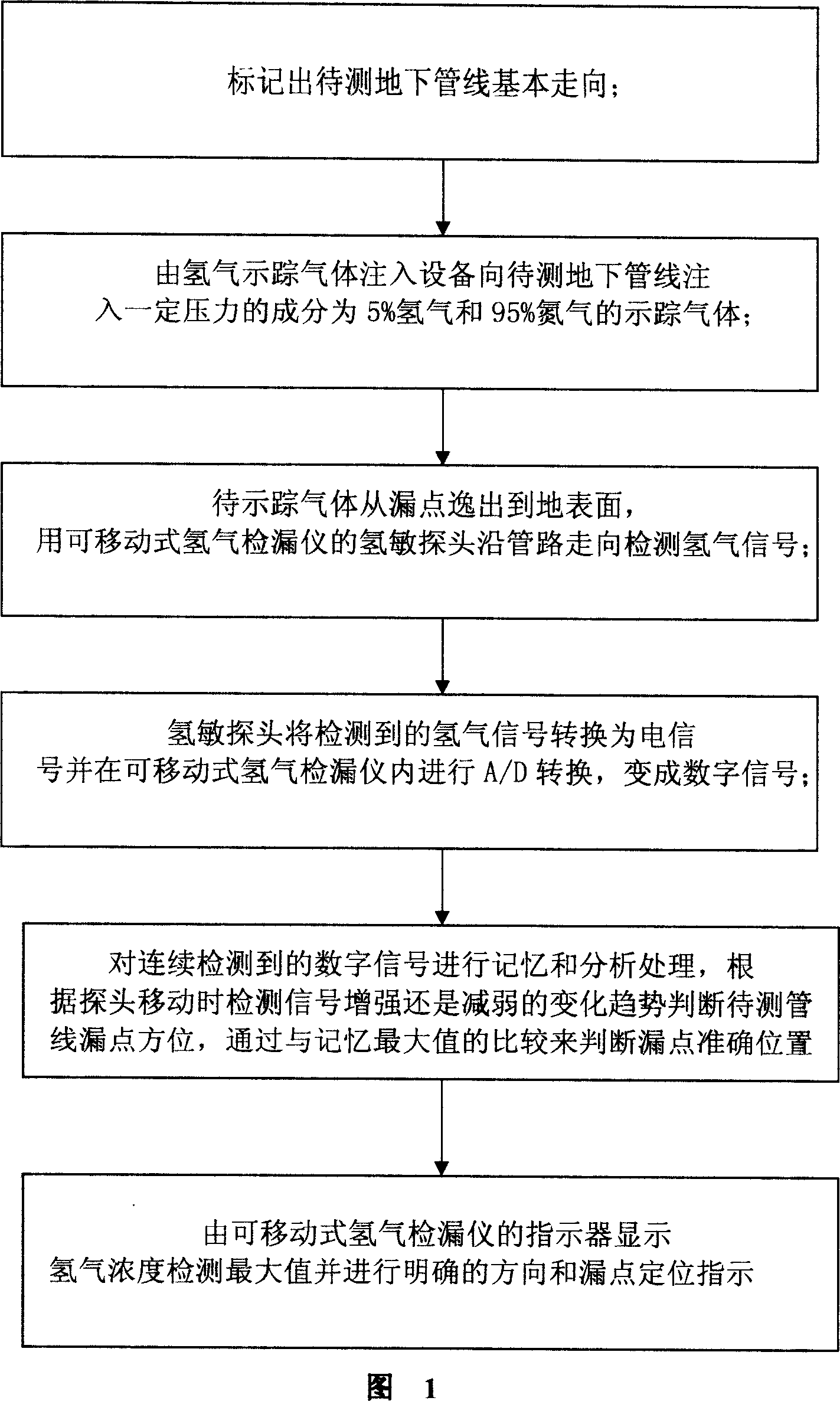
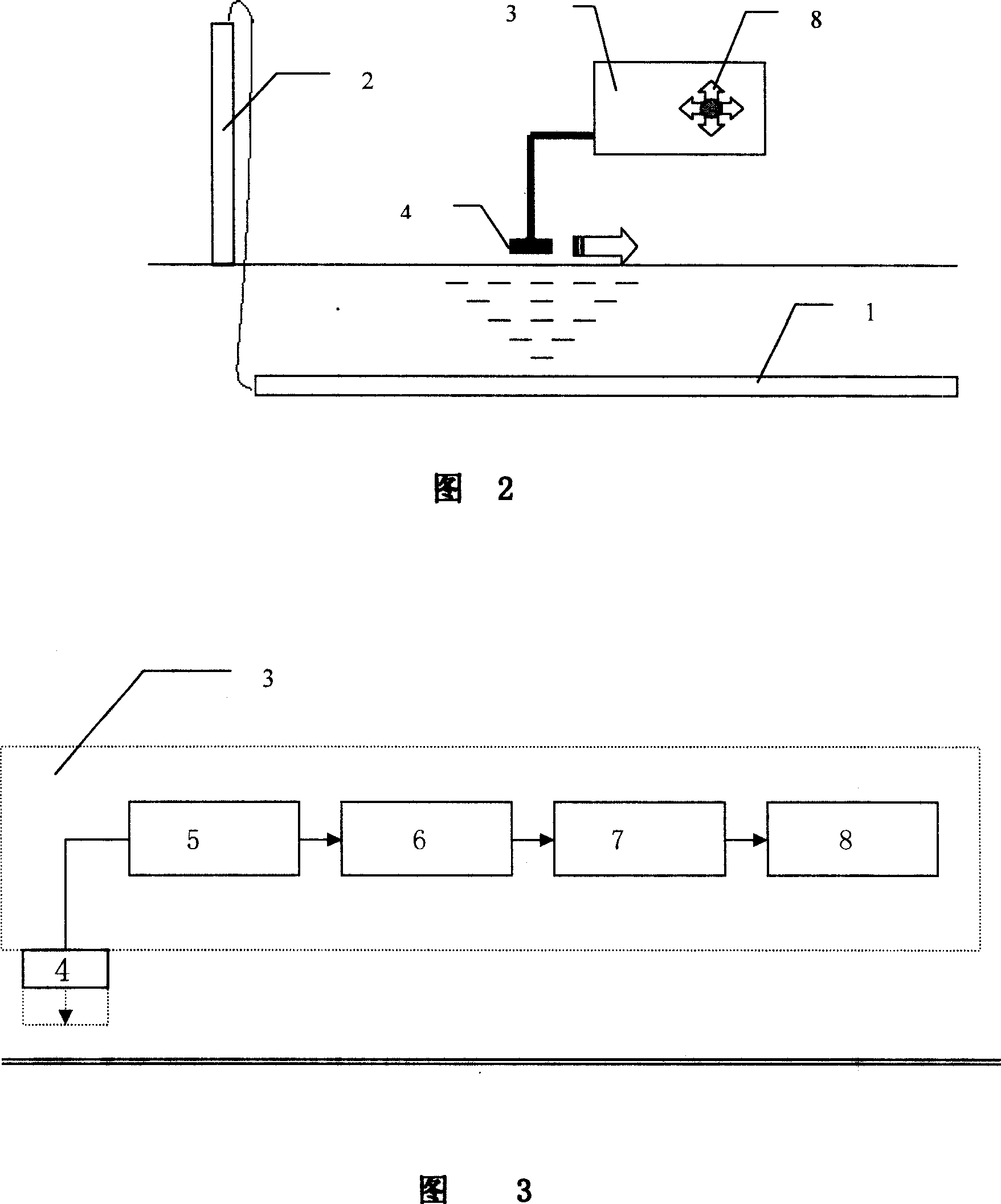
[0035] In Fig. 1, the underground pipeline leakage detection method provided by the present invention comprises underground pipeline, hydrogen tracer gas injection equipment and movable hydrogen leak detector, and its specific method is:

[0036] Mark the basic direction of the underground pipeline to be tested;

[0037] The hydrogen tracer gas injection equipment injects tracer gas with a certain pressure composition of 5% hydrogen and 95% nitrogen into the underground pipeline to be tested;

[0038] When the tracer gas escapes from the leak point to the ground surface, use the hydrogen sensitive probe of the portable hydrogen leak detector to detect the hydrogen signal along the pipeline;

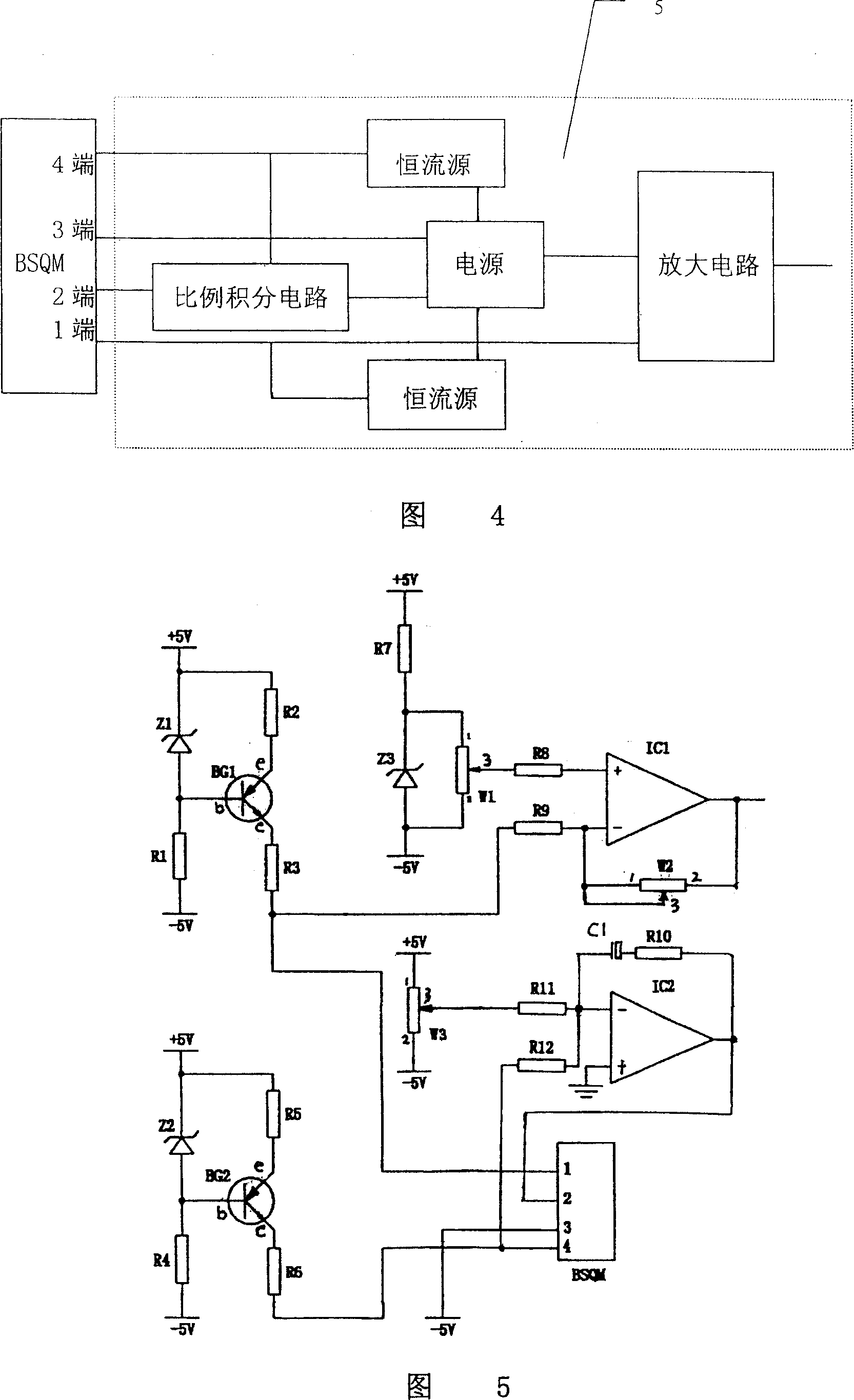
[0039] The hydrogen sensitive probe converts the detected hydrogen signal into an electrical signal and performs A / D conversion in the portable hydrogen leak detector to become a digital signal;

[0040] Carry out memory storage, analysis and processing of the continuously detected digit...


PUM


Abstract

This invention provides a leakage test method and a device including: marking a basic tendency of an underground line to be tested, injecting a tracer gas in a certain pressure composition of 5% hydrogen and 95% nitrogen to the line, testing the H2 signal along the tendency of the pipeline with a H2-sensitive probe of a movable hydrogen leak detector, converting the test signal to an electric signal then converting it to a digital signal by A/D conversion, memorizing and analyzing the continuously tested digital signals to judge the leakage orientation based on the change trend weak or strong of the test signal and judging the accurate position of the leak point by comparing with the maximum value of the memory and an indicator displays the maximum value of the concentration of the tested hydrogen and indicates the location of the direction and leakage definitely. Advantage: direct indication, accurate location to reduce work intensity of test.

Description

technical field [0001] The invention belongs to the field of pipeline leakage detection, and in particular relates to a method and a device for detecting underground pipeline leakage by using a hydrogen tracing method. Background technique [0002] In order to meet the production needs of urban and rural life and industrial fields, people have laid a large number of pipeline projects underground, and use these pipelines to transport water, oil, steam, gas (such as liquefied petroleum gas, natural gas) industrial products, etc. These pipelines are usually pressure pipelines. Before the newly laid pressure pipelines are put into use, pipeline leak detection is usually required to confirm that there is no leakage to ensure safe operation. In more cases, after the underground pipeline is put into use, it often causes leakage due to natural or man-made reasons such as pipeline corrosion and engineering construction, which affects people's daily life and normal production of enter...

Claims


Application Information

Patent Timeline
IPC IPC(8): F17D5/02
CPCY02E60/34
Inventor 耿玉桐
Owner ZIBO SIKE OPTOELECTRONICS TECH
Why Eureka
Try Eureka