

Dewatering technology of mud and its device
A technology of sludge dewatering and dewatering device, applied in the direction of dewatering/drying/concentrating sludge treatment, can solve the problems of high energy consumption, difficult to popularize and use, etc., and achieve the effect of low water content
- Summary
- Abstract
- Description
- Claims
- Application Information
AI Technical Summary
Problems solved by technology
Method used
Image

Examples
Embodiment 1
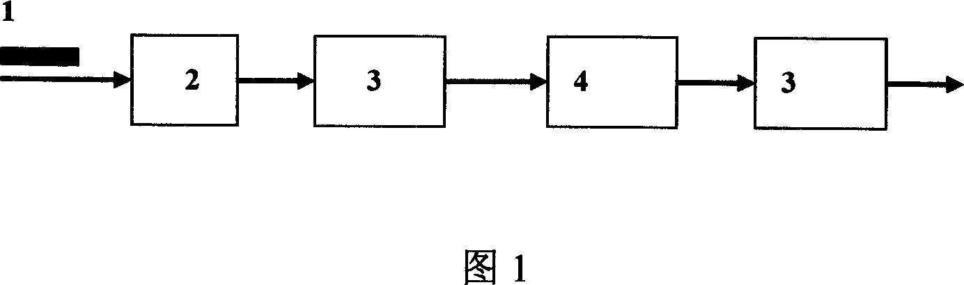
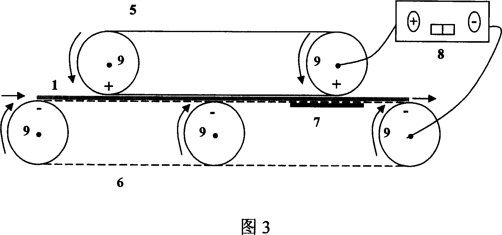
[0029]As shown in Figure 1, the flocculated and concentrated sewage plant sludge 1 with a water content of 95% is sent to the belt filter press 2 for mechanical dehydration by press filtration. When the sludge is difficult to dewater by mechanical press filtration, the dehydration rate becomes slower. (the moisture content of the sludge is 82%), enter the self-made belt pressure combined electro-osmosis dehydration device 3 for rapid dehydration. The schematic diagram of the structure of the device 3 is shown in Figure 3. The dewatered sludge 1 enters from one end of the device 3. Through the rotation of the roller shaft 9, it is driven by the anode metal rolling belt 5 and the cathode metal rolling belt 6 with holes. The sludge proceeds to the end of the device 3, and the sludge is dehydrated by the pressing action of the anode metal rolling belt 5 and the perforated cathode metal rolling belt 6, and when the DC power supply 8 is started, the anode metal rolling belt 5 and the...
Embodiment 2
[0031] The process flow and device are as in Example 1, except that: the lower rear sludge moisture accumulation area on the cathode side of the self-made belt pressure synergistic electroosmotic dehydration device 3 adopts polyurethane water-absorbing material 7 to carry out adsorption and dehydration treatment (as shown in Figure 3 shown), the sludge in the process of pressure-assisted electro-osmosis dehydration and ultrasonic sludge conditioning is heated by hot air at a temperature of 50°C, the DC voltage gradient in pressure-assisted electro-osmotic dehydration is 3V / mm, and the ultrasonic frequency is 100kHz, the specific power input is 20kWh / T dry solid, and the ultrasonic conditioning, that is, the pressure-assisted electroosmosis dehydration process is repeated 5 times. After the sludge dewatering, the sludge moisture content is 61.9%, and the filter cake thickness is 2mm.
Embodiment 3
[0033] The process flow is the same as in Example 2, the difference is: compared with the pressure-assisted electro-osmotic dehydration device in Embodiment 1 and Example 2, the pressure-assisted electro-osmotic dehydration device in this process combines the ultrasonic contact 16, the ultrasonic contact 16 Enter the sludge from the anode side of the sludge for ultrasonic conditioning. The schematic diagram of the structure is shown in Figure 4. The device realizes the superposition of the three effects of ultrasonic modification, compression and electroosmosis of DC electric field. The sludge is heated with hot air, the heating temperature is 40°C, the DC voltage gradient is 1.5V / mm, the ultrasonic frequency is 60kHz, the specific power input is 30kWh / T dry solid, and the ultrasonic conditioning, ultrasonic and pressure synergistic electroosmosis dehydration process is repeated for 3 times Second, the moisture content of the sludge after sludge dehydration is 65.9%, and the t...
PUM
| Property | Measurement | Unit |
|---|---|---|
| Thickness | aaaaa | aaaaa |
Abstract
Description
Claims
Application Information