

Method for producing luminous element with high-illuminating effect
A light-emitting element and manufacturing method technology, which is applied in the direction of electrical components, semiconductor devices, circuits, etc., can solve the problems such as the inability to effectively remove alumina slag, and achieve the effects of avoiding fragmentation problems, increasing yield, and improving brightness
- Summary
- Abstract
- Description
- Claims
- Application Information
AI Technical Summary
Problems solved by technology
Method used
Image

Examples
Embodiment Construction
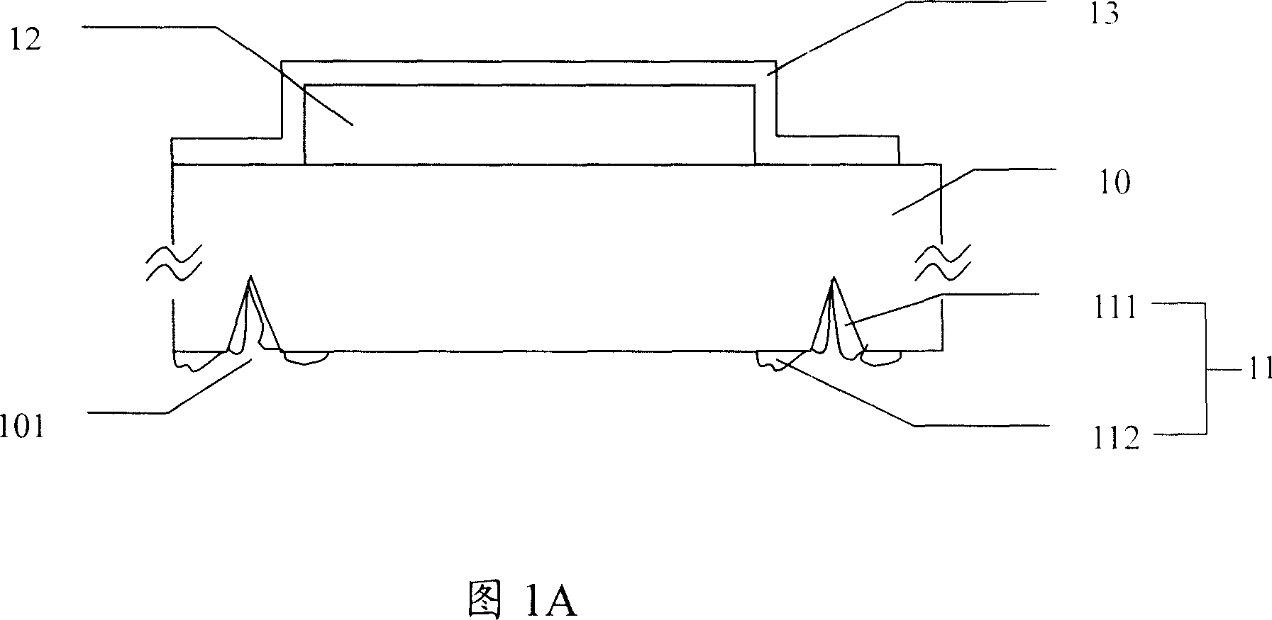
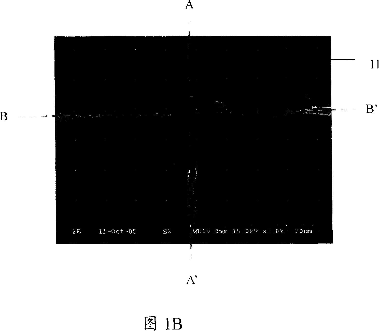
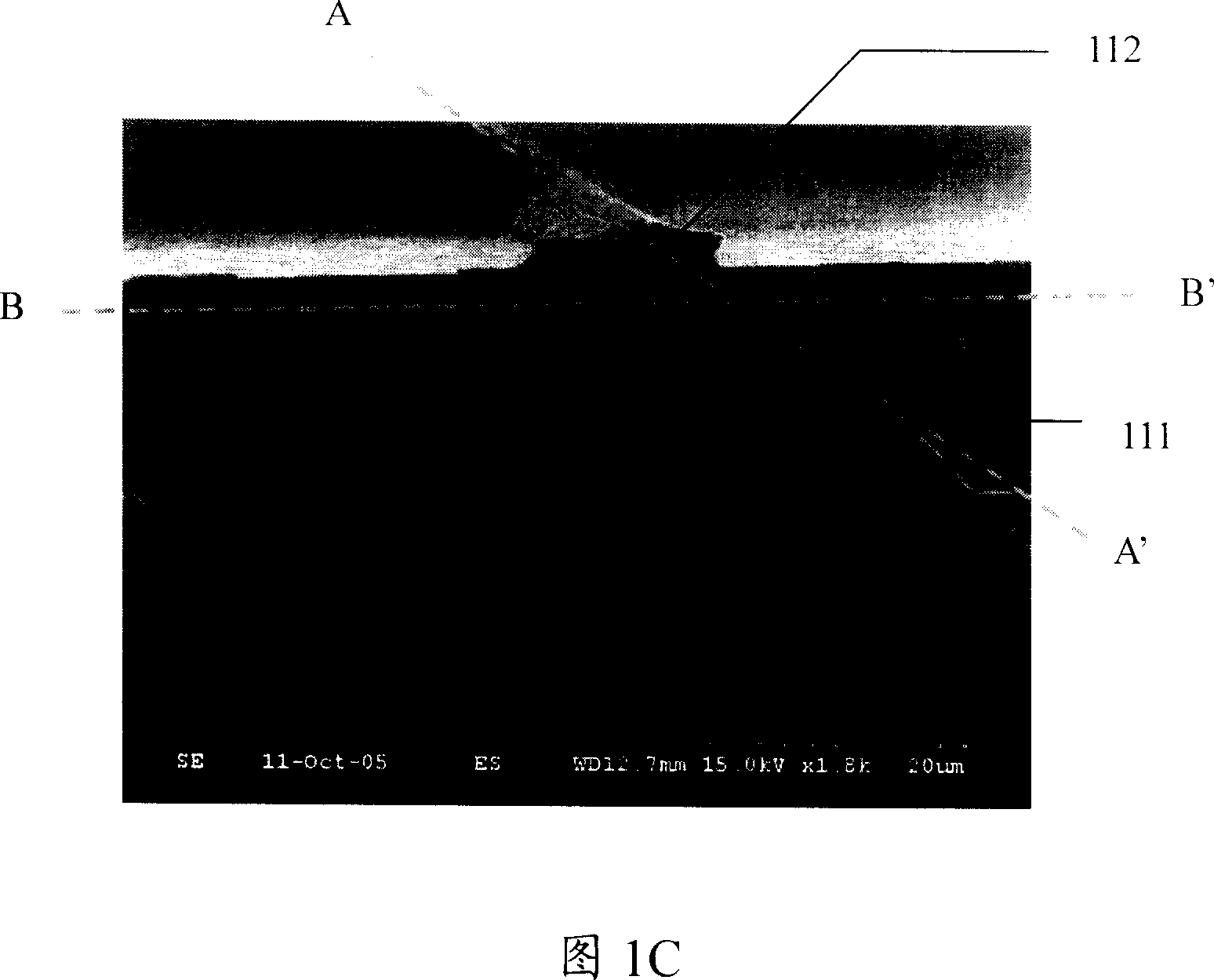
[0031] Please refer to FIGS. 1A-1C , according to a method for manufacturing a high-luminous-efficiency light-emitting element 1 according to a preferred embodiment of the present invention, the steps include on the first surface of a substrate 10 with a first upper surface and a first lower surface. A light-emitting stack 12 is formed on the surface, wherein the light-emitting stack includes a second upper surface and a second lower surface, and the second lower surface faces the substrate 10, and a first layer is coated on the second upper surface of the light-emitting stack. a protective layer 13, cutting the light-emitting element 1 with a laser beam from the lower surface of the substrate, and placing the light-emitting element 1 with the first protective layer 13 in a heated acidic solution for a period of time, passing through the hot acidic solution, By-products are removed. In the process of laser beam cutting the light-emitting element in this embodiment, the laser b...
PUM
 Abstract
Description
Claims
Application Information