Plasma cutter

A cutting device, plasma technology, applied in the direction of plasma welding equipment, welding/welding/cutting items, manufacturing tools, etc., can solve the problems of reduced cutting surface quality, poor fluidity, etc., and achieve the effect of good cutting quality

Inactive Publication Date: 2007-07-04
KOMATSU SANKI
View PDF2 Cites 4 Cited by
  • Summary
  • Abstract
  • Description
  • Claims
  • Application Information

AI Technical Summary

Problems solved by technology

[0002] In the plasma cutting of stainless steel, the chromium contained in the stainless steel is oxidized during the cutting process, and the chromium oxide adheres to the cutting surface due to its poor fluidity, reducing the quality of the cutting surface

Method used


Image

  • Plasma cutter
  • Plasma cutter

Examples


Embodiment Construction

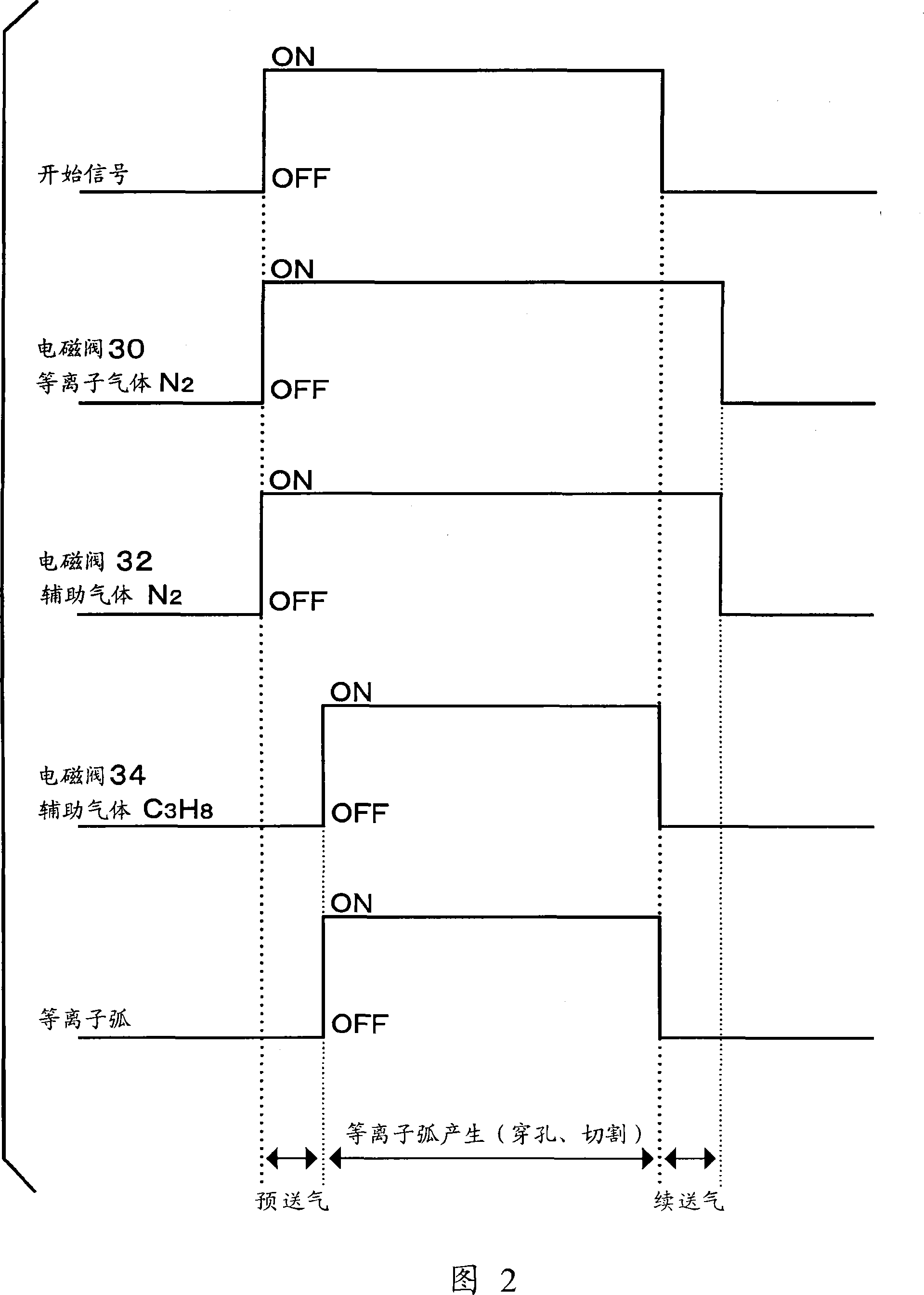
[0027] Embodiments of the present invention will be described below with reference to the drawings. As described below, this embodiment uses an inert gas such as nitrogen as the plasma gas, and uses a combustible gas with a specific gravity heavier than air and has reducing properties or a mixture of the combustible gas and an inert gas, such as a mixture of nitrogen and propane, as an auxiliary gas. Thereby stainless steel can be cut to obtain good quality.

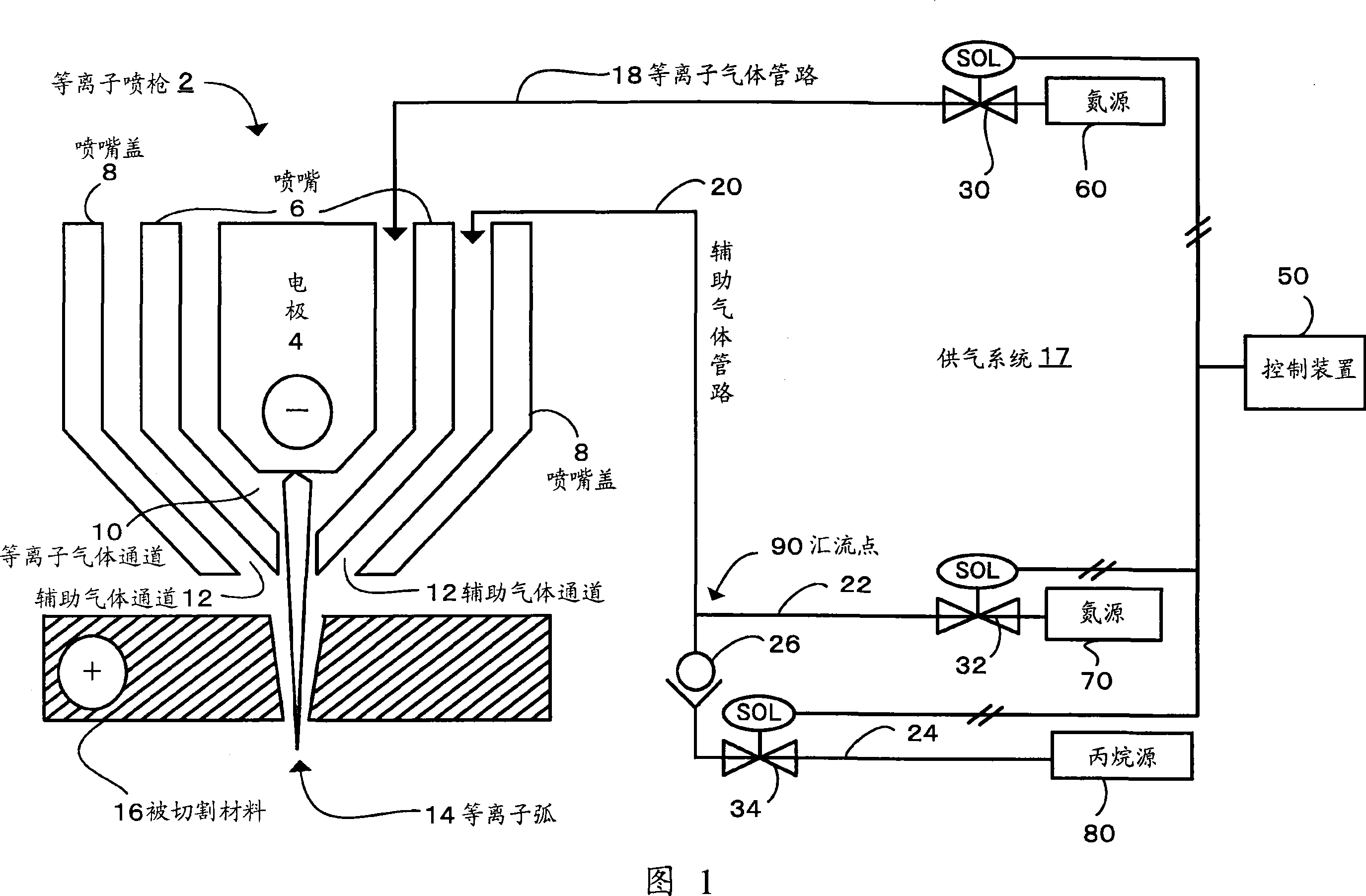
[0028] FIG. 1 is a schematic configuration diagram of a plasma cutting apparatus according to an embodiment of the present invention.

[0029] As shown in FIG. 1 , the plasma torch 2 is in the shape of multiple cylinders as a whole, with an electrode 4 at its center, a nozzle 6 around the outside of the electrode 4 , and a nozzle cover 8 around the outside of the nozzle 6 . A gas supply system 17 is connected to the plasma torch 2 .

[0030] The gas supply system 17 includes: a plasma gas pipeline 18 for supplying plas...


PUM


Abstract

A plasma cutter capable of cutting stainless steel while ensuring excellent quality. To plasma torch (6), there are fed as a plasma gas an inert gas (nitrogen) and as an assist gas a combustible gas (propane) that has a specific gravity greater than that of air and has reducing property or a mixed gas consisting of the above combustible gas (propane) and inert gas (nitrogen). The combustible gas (propane) contained in the assist gas is not fed in a preflow zone and afterflow zone and fed only in a plasma arc generation zone.

Description

technical field [0001] The invention relates to a plasma cutting method for cutting stainless steel and a plasma cutting device for cutting stainless steel by implementing the method. Background technique [0002] In the plasma cutting of stainless steel, the chromium contained in the stainless steel is oxidized during the cutting process, and the chromium oxide adheres to the cut surface due to its poor fluidity, degrading the quality of the cut surface. As a countermeasure against this problem, prior arts regarding the composition of plasma gas and assist gas as described below are known. The first prior art uses nitrogen or air as a plasma gas, and methane or a mixed gas of methane and air as an assist gas (Patent Document 1). In addition, the second prior art uses air or a mixed gas of air and nitrogen as a plasma gas, and hydrogen, or a mixed gas containing hydrogen, or hydrocarbon gas as an assist gas (Patent Document 2). [0003] Patent Document 1: US Patent No. 5,4...

Claims


Application Information

Patent Timeline
Patent Type & Authority Applications(China)
IPC IPC(8): B23K10/00B23K103/04
CPCB23K2203/04B23K10/006B23K10/00B23K2103/05
Inventor 山口义博藏冈一浩
Owner KOMATSU SANKI
Why Eureka
Try Eureka