Group 13 element nitride crystal layer and function element

a technology of nitride crystal layer and functional element, which is applied in the direction of polycrystalline material growth, crystal growth process, chemically reactive gas, etc., can solve the problem of not increasing light output, and achieve the effect of suppressing current leakage, improving crystal growth conditions, and suppressing current leakag

Active Publication Date: 2018-06-19
NGK INSULATORS LTD
View PDF14 Cites 0 Cited by
  • Summary
  • Abstract
  • Description
  • Claims
  • Application Information

AI Technical Summary

Benefits of technology

[0014]An object of the present invention is to provide a group 13 element nitride crystal layer having a desired conductivity and to effectively utilize the conductivity of the crystal layer to improve its function.
[0026]As a result of the detailed investigation of the mechanism of the current leakage described above, it was found that regions exhibiting higher conductivity, in a cross-sectional structure of the group 13 element nitride crystal layer, had deteriorated crystallinity and facilitated the flow of current, thus causing a local current concentration, which resulted in the occurrence of the current leakage. Specifically, the microscope thermography could successfully detect a temperature rise in the location where the current concentration occurred.
[0029]Based on the finding, the present inventors successfully formed a cross-sectional structure of the crystal layer, in which the low carrier concentration regions are formed into a net-like shape and the high carrier concentration regions are surrounded by the low carrier concentration regions having the net-like shape, by improving crystal growth conditions. The inventors further successfully suppressed the current leakage between the pair of the main surfaces of the crystal layer by obtaining such a cross-sectional structure. This can suppress the current leakage caused by increasing the voltage applied to the crystal layer, thereby enabling to effectively utilize the conductivity of the crystal layer to improve its function.

Problems solved by technology

However, even when the conductivity of the above-mentioned crystal layer was actually improved, for example, by increasing a current in a vertically structured LED, a phenomenon was observed in which the light output was not increased.

Method used


Image

  • Group 13 element nitride crystal layer and function element
  • Group 13 element nitride crystal layer and function element
  • Group 13 element nitride crystal layer and function element

Examples


example 1

(Production of Seed Crystal Substrate)

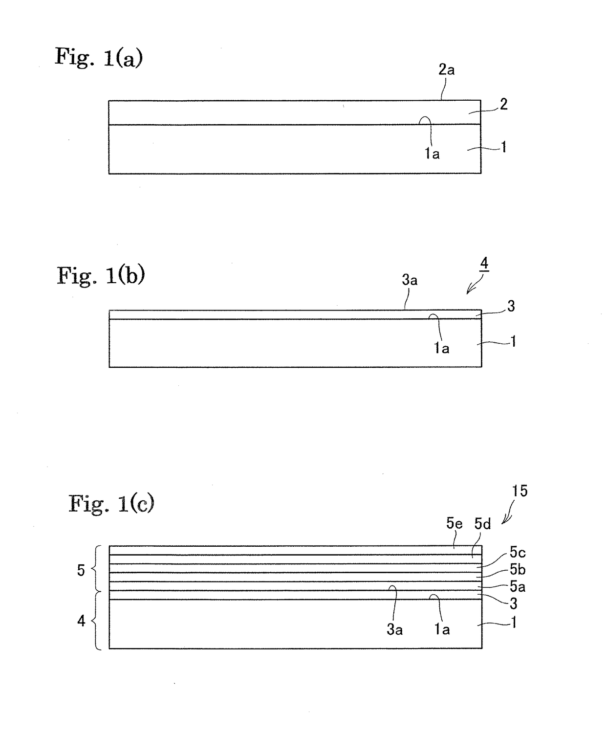
[0123]A low temperature GaN buffer layer was deposited to 20 nm at 530° C. on a c-face sapphire substrate having a diameter of 2 inches and a thickness of 500 microns (the substrate having an off angle of 0.5 degrees in the a-axis direction was selected) by the MOCVD method. Then, a GaN film having a thickness of 2 μm was laminated at 1050° C. on the buffer layer. The defect density was 1×10⁹ / cm2 as measured by TEM observation. The laminated substrate was cleaned ultrasonically in an organic solvent and ultrapure water for 10 minutes each and then dried to obtain a seed crystal substrate.

[0124](GaN Crystal Growth by Liquid Phase Method)

[0125]Ga metal and Na metal were weighed in a molar ratio of 27:73 inside a glove box filled with inert gas and placed onto the bottom of an alumina crucible together with the seed crystal substrate. Ge was added in an amount of 0.8 mol % with respect to the amount of Ga for imparting conductivity. Three of such c...


PUM

PropertyMeasurementUnit
temperatureaaaaaaaaaa
temperaturesaaaaaaaaaa

Abstract

A crystal layer of a nitride of a group 13 element includes a pair of main surfaces. The crystal layer includes high carrier concentration regions having a carrier concentration of 1×10¹⁸ / cm3 or more and low carrier concentration regions having a carrier concentration of 9×10¹⁷ / cm3 or less, viewed in a cross section perpendicular to the main surfaces of the crystal layer. Each of the low carrier concentration regions is extended in an elongated shape. The low carrier concentration regions include association parts. The low carrier concentration regions are extended continuously between the pair of the main surfaces.

Description

TECHNICAL FIELD[0001]The present invention relates to a group 13 element nitride crystal layer and a functional element. The present invention can be applied, for example, to technical fields requiring high quality, more specifically, a blue LED with high color rendering properties expected to be the next-generation light source that can substitute for a fluorescent lamp, a blue-violet laser for a high-speed and high-density optical memory, a power device used in an inverter for a hybrid vehicle, and the like.BACKGROUND ART[0002]Recently, studies are actively conducted to produce semiconductor devices, such as a blue LED, a white LED, and a blue-violet semiconductor laser, using a group 13 element nitride such as gallium nitride, and to apply the resulting semiconductor devices to various electronic apparatuses.[0003]With the expansion of the uses of the white LED, there has been an increasing demand for further improving performance of an LED chip. For the LED chip, improving perfo...

Claims


Application Information

Patent Timeline
Patent Type & Authority Patents(United States)
IPC IPC(8): C30B29/40H01L33/32C23C16/34C30B19/02C30B19/12C30B25/20
CPCC30B29/406C23C16/34C30B19/02C30B19/12C30B25/20H01L33/32
Inventor IWAI, MAKOTOYOSHINO, TAKASHI
Owner NGK INSULATORS LTD
Why Eureka
Try Eureka