

Electric drive system enhancement using a DC-DC converter
- Summary
- Abstract
- Description
- Claims
- Application Information
AI Technical Summary
Benefits of technology
Problems solved by technology
Method used
Image

Examples
Embodiment Construction
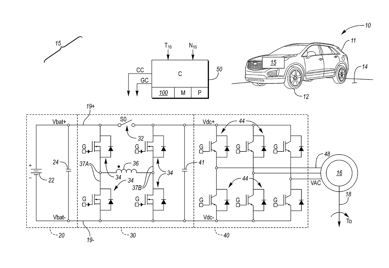
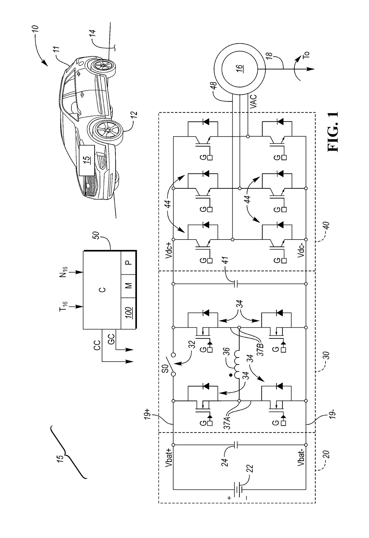
[0021]Referring to the drawings, wherein like reference numbers refer to like components throughout the several views, FIG. 1 depicts a schematic example vehicle 10 having a body 11 and an electric drive system 15. The vehicle 10 may be configured as a motor vehicle as shown, and therefore may be equipped with wheels 12 in rolling contact with a road surface 14. While the vehicle 10 of FIG. 1 is an example of a type of system benefiting from use of the present drive system 15, other applications for the drive system 15 may be readily envisioned, including but not limited to stationary power plants, mobile platforms, and other types of land, air, or marine vehicles.
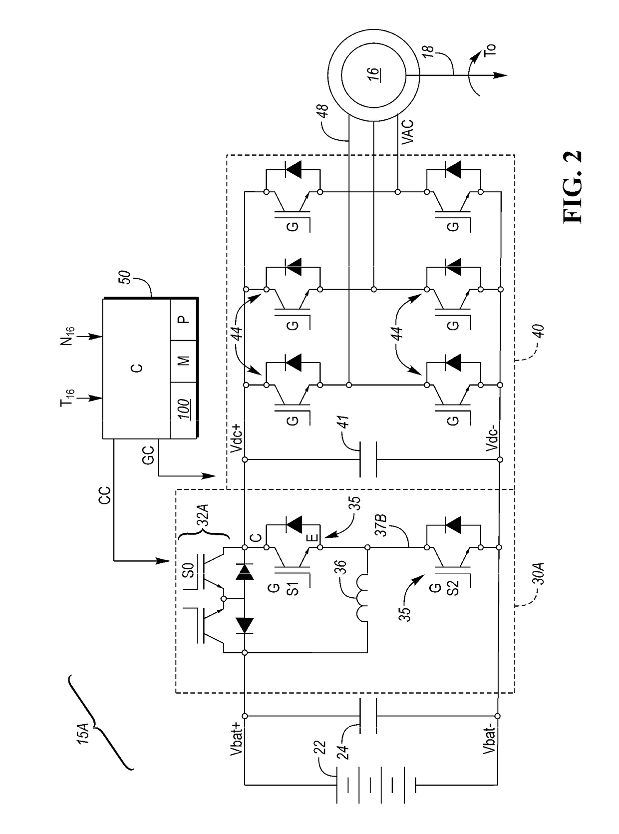
[0022]The electric drive system 15 may include a polyphase electric machine 16 having a rotatable output shaft 18. When the electric machine 16 is energized via application of an alternating current (AC) polyphase voltage (VAC) to individual phase windings 48 of the electric machine 16, motor torque (arrow TO) is generated...
PUM
 Abstract
Description
Claims
Application Information