Working fluid for heat cycle, composition for heat cycle system, and heat cycle system

a technology of working fluid and heat cycle, which is applied in the direction of space heating and ventilation, lighting and heating apparatus, heating types, etc., can solve the problems of high equipment pressure, high risk of refrigerant leakage out to the air, and global warming, and achieve low discharge temperature, low temperature glide, and high durability

Active Publication Date: 2018-11-20
ASAHI GLASS CO LTD
View PDF6 Cites 3 Cited by
  • Summary
  • Abstract
  • Description
  • Claims
  • Application Information

AI Technical Summary

Benefits of technology

[0029]The working fluid for heat cycle and the composition for a heat cycle system of the present invention have a low temperature glide, a sufficiently low discharge temperature and high durability. Further, they have less influence over global warming and are excellent in the cycle performance (capacity).
[0030]Further, the heat cycle system of the present invention, which employs the working fluid for heat cycle of the present invention, has high durability, has less influence over global warming and is excellent in the cycle performance (capacity) and the energy efficiency.

Problems solved by technology

However, it is pointed out that HFCs may cause global warming.
Further, in an automobile air-conditioning system, the refrigerant is highly likely to leak out to the air e.g. from a connection hose or a bearing.
However, with carbon dioxide, the equipment pressure tends to be extremely high as compared with HFC-134a, and accordingly there are many problems to be solved in application to all the automobiles.
HFC-152a has a combustion range, and has a problem for securing the safety.
However, HFOs disclosed in Patent Documents 1 and 2 are insufficient in the cycle performance (capacity) and among such HFOs, one having a low proportion of fluorine atoms has combustibility.
Further, HFOs disclosed in Patent Document 2 are also insufficient in the cycle performance (capacity).
Further, if a compressor discharge gas temperature (hereinafter sometimes referred to as a discharge temperature) when a working fluid for heat cycle is applied to a refrigerating cycle is high, the heat resistance of a material constituting the compressor, a refrigerant oil usually contained in a composition for a heat cycle system in addition to the working fluid, an organic compound and the like may be impaired.

Method used


Image

  • Working fluid for heat cycle, composition for heat cycle system, and heat cycle system
  • Working fluid for heat cycle, composition for heat cycle system, and heat cycle system
  • Working fluid for heat cycle, composition for heat cycle system, and heat cycle system

Examples


examples

[0133]Now, the present invention will be described in further detail with reference to Examples. However, it should be understood that the present invention is by no means restricted to such specific Examples.

Ex. 1

(Evaluation of Self-Decomposition Property)

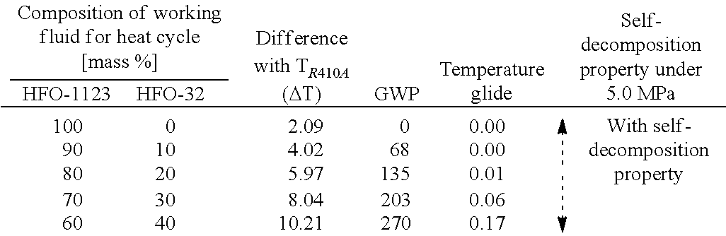
[0134]With respect to a working fluid for heat cycle comprising HFO-1123 and HFC-32, self-decomposition property was evaluated under pressure conditions up to 7.0 MPa. The self-decomposition property was evaluated in equipment in accordance with method A recommended as equipment for measurement of the combustion range of a gas mixture containing halogen, by individual notifications in High Pressure Gas Safety Act.

[0135]A working fluid for heat cycle having HFO-1123 and HFC-32 mixed in a proportion as identified in Table 1 was enclosed in a spherical pressure resistant reactor having an internal capacity of 650 cm3 and having a temperature in the interior controlled to a range of from 190° C. to 210° C. by heating by a heater from ...


PUM

PropertyMeasurementUnit
pressureaaaaaaaaaa
pressureaaaaaaaaaa
global warming potentialaaaaaaaaaa

Abstract

To provide a working fluid for heat cycle which has a small temperature glide, a sufficiently low discharge temperature, high durability and less influence over global warming, and with which a heat cycle system excellent in the system maintenance properties and the cycle performance (capacity) is achieved, a composition for a heat cycle system, and a heat cycle system. A working fluid for heat cycle, which contains trifluoroethylene and difluoromethane, wherein the proportion of the total amount of trifluoroethylene and difluoromethane based on the entire amount of the working fluid for heat cycle is higher than 90 mass % and at most 100 mass %, and the mass ratio represented by trifluoroethylene / difluoromethane in the working fluid for heat cycle is from 41 / 59 to 59 / 41, a composition for a heat cycle system, and a heat cycle system employing the composition.

Description

[0001]This application is a continuation of PCT Application No. PCT / JP2015 / 054661, filed on Feb. 19, 2015, which is based upon and claims the benefit of priority from Japanese Patent Application No. 2014-038614 filed on Feb. 28, 2014. The contents of those applications are incorporated herein by reference in their entireties.TECHNICAL FIELD[0002]The present invention related to a working fluid for heat cycle containing trifluoroethylene and difluoromethane, a composition for a heat cycle system comprising the working fluid, and a heat cycle system.BACKGROUND ART[0003]Heretofore, as a working fluid such as a refrigerant for a refrigerator, a refrigerant for an air-conditioning apparatus, a working fluid for power generation system (such as exhaust heat recovery power generation), a working fluid for a latent heat transport apparatus (such as a heat pipe) or a secondary cooling fluid, a chlorofluorocarbon (CFC) such as chlorotrifluoromethane or dichlorodifluoromethane or a hydrochloro...

Claims


Application Information

Patent Timeline
Patent Type & Authority Patents(United States)
IPC IPC(8): C09K5/04F24F1/02
CPCC09K5/045F24F1/022C09K2205/22C09K2205/126C09K2205/122
Inventor OKAMOTO, HIDEKAZUFUKUSHIMA, MASATOKAWAGUCHI, SATOSHIKADOWAKI, YOSHINOBUOTSUKA, TETSUOUENO, KATSUYAKURASHIMA, KAZUYOSHI
Owner ASAHI GLASS CO LTD
Why Eureka
Try Eureka