Method for manufacturing a solid electrolyte sensor element for detecting at least one property of a measuring gas in a measuring gas chamber, containing two porous ceramic layers

a technology of solid electrolyte and sensor element, which is applied in the direction of instruments, measurement devices, scientific instruments, etc., can solve the problems of affecting the heat-up behavior of the sensor element, affecting the robustness of thermal shock, and water droplets forming in the exhaust pipe, so as to achieve the effect of increasing the thermal mass and improving the robustness against thermal shock

Inactive Publication Date: 2019-01-15
ROBERT BOSCH GMBH
View PDF14 Cites 0 Cited by
  • Summary
  • Abstract
  • Description
  • Claims
  • Application Information

AI Technical Summary

Benefits of technology

[0007]Therefore, a method for manufacturing a sensor element for detecting at least one property of a measuring gas in a measuring gas chamber as well as a sensor element which is manufacturable according to this method are provided which at least largely avoid the disadvantages of known methods and sensor elements, in which the robustness against thermal shock may be improved without increasing the thermal mass, and without causing prior damage.
[0022]Due to a thermal shock protective layer being made of multiple individual layers which are optimally adapted to particular requirements, for example thermal shock protection, heat conductivity, water permeability, heat capacity, and wettability, the impairment of the functioning and dynamics of the lambda sensor may be reduced by the applied thermal shock protective layer. For example, the layers may differ with respect to their porosity. At the same time, however, by varying the selected ceramic, for example with an inner layer of zirconium dioxide and an outer layer of aluminum oxide, the heat conductivity and the heat capacity may also be adapted, partially independently of the porosity. The layer thickness and the thermal mass of the thermal shock protective layer may thus be kept preferably small. In addition, a high porosity of the inner thermal shock protective layer may thus be achieved, as the result of which the thermal mass of the thermal shock protective layer is decoupled from the sensor element. The heating voltage requirement and the fast light-off time may be reduced by the thermal decoupling of the inner thermal shock protective layer. The permeability of water may be reduced by the use of a thin, finely porous outer layer; i.e., the layer becomes hydrophobic without the measuring gas entry to the measuring electrodes being impermissibly reduced. In other words, the outer layer has the function of a diaphragm. In particular, the inlet area of a gas inlet port of the base ceramic of the sensor element is significantly enlarged by the roughly porous inner layer of the thermal shock protective layer, and therefore the gas inlet restriction by the outer, comparatively more dense thermal shock protective layer is effectively decreased. For a manufacturing variation of the permeability of the outer layer, this results in even smaller variations in the gas inlet, and thus in the increase of the characteristic curve of the sensor element. Due to the use of various ceramics, the thermal properties, for example heat conductivity, thermal expansion, and heat capacity, may be set as a partial function of the porosity. In addition, the thermomechanical stresses between the sensor element and the thermal shock protective layer may be reduced, so that no change in the porosity occurs due to microcracks, or macroscopic cracks do not result in failure of the thermal shock protective layer or of the sensor element. The dynamic response characteristic of the sensor element during rapid gas exchanges may thus be improved, since the gas storage capacity of the thin inner, highly porous thermal shock protective layer is reduced due to the smaller open pore volume.
[0023]Another basic concept of the present invention is to optimize the thermal shock protective layer by inorganic porous layers on ceramic exhaust gas sensors. The structure of the thermal shock protective layer is adapted to the dynamics and the thermal shock protection in a targeted manner. A design of the thermal shock protective layer is particularly advantageous in which the inner layer has a high porosity. This should be achieved by the uniform distribution of large pores. The outer layer of the thermal shock protective layer is made up of a layer having a lower, finely distributed porosity. Accordingly, the high porosity of the inner thermal shock protective layer represents a very good thermal insulation between the solid electrolyte and the rest of the thermal shock protective layer, since, due to the high proportion of pores which contain large quantities of air, the heat conductivity is low compared to the solid electrolyte. The solid electrolyte may therefore be heated up more rapidly; i.e., a shorter fast light-off time is achieved since the mass of the thermal shock protective layer is thermally decoupled from the solid electrolyte. The decoupling of the thermal masses of the thermal shock protective layer from the solid electrolyte also results in a lower heating voltage requirement, since the cooling of the thermal shock protective layer is not directly transferred to the surface of the solid electrolyte. A smooth surface with little roughness is achieved by setting a fine porosity of the outer layer. This prevents the penetration of water into the protective layer, which would increase the fast light-off time. There is also an improved thermal shock robustness on account of the reduced water permeability due to producing a smooth surface. To allow water which has penetrated into the thermal shock protective layer to be able to escape during rapid heat-up of the solid electrolyte, the outer layer, which acts as a diaphragm, on the one hand must be mechanically stable to be able to withstand the rapidly rising pressure of the water vapor, and on the other hand must be sufficiently porous to allow the water vapor to pass from the inside to the outside.
[0024]For example, the multi-ply thermal shock protective layer is implemented by a combination of plasma coating and dip coating. In addition, all combinations of plasma coating, dip coating, and spray coating are implementable for producing a multi-ply thermal shock protective layer. The multi-ply thermal shock protection may be achieved by various material compositions, using the same application method, or by using various application methods. For example, the thermal shock protective layer is implemented in a combination of atmospheric plasma spraying and a sol-gel suspension. The sol-gel suspension forms a smooth and finely porous layer on the plasma-sprayed surface. The penetration of water into the plasma-sprayed layer is thus prevented. Due to the water-free plasma-sprayed layer, no heat output for the evaporation of water is required when the sensor element is heated up, as the result of which the fast light-off time may be reduced.

Problems solved by technology

This results in the formation of water droplets in the exhaust pipe.
The heated-up ceramic of the lambda sensor may be damaged or even destroyed due to thermal stresses or ruptures in the sensor ceramic due to the impact of water droplets.
Optimizing the sensor element with regard to the two mentioned influencing variables results in various conflicting objectives.
Thus, a thick thermal shock protective layer reliably protects against hydrolock, but as additional mass, adversely affects the heat-up behavior of the sensor element.
The thermal shock protective layer impairs the dynamics of the lambda sensor.
In addition, the use of aluminum oxide as a thermal shock protective layer material having good heat conductivity may result in increased heat discharge from the sensor element.
Lastly, although slimming down the ceramic substrate allows quicker heat-up times, it makes the sensor element more mechanically fragile.
Moreover, the open porosity of plasma-sprayed layers changes due to thermal aging, so that the functioning of “voltage-jump” sensors as well as broadband sensors having a covered gas inlet port is impaired.
The connection between the sensor element and the layer provided by the inherent bond of the thermal shock protective layer is not entirely satisfactory.
Continued particle growth and the aggregation of sol particles to form secondary particles result in an increase in viscosity.
A porosity above 80% is not included for technical reasons, since it may lower the stability of the layer.
This prevents the penetration of water into the protective layer, which would increase the fast light-off time.

Method used


Image

  • Method for manufacturing a solid electrolyte sensor element for detecting at least one property of a measuring gas in a measuring gas chamber, containing two porous ceramic layers
  • Method for manufacturing a solid electrolyte sensor element for detecting at least one property of a measuring gas in a measuring gas chamber, containing two porous ceramic layers

Examples


Embodiment Construction

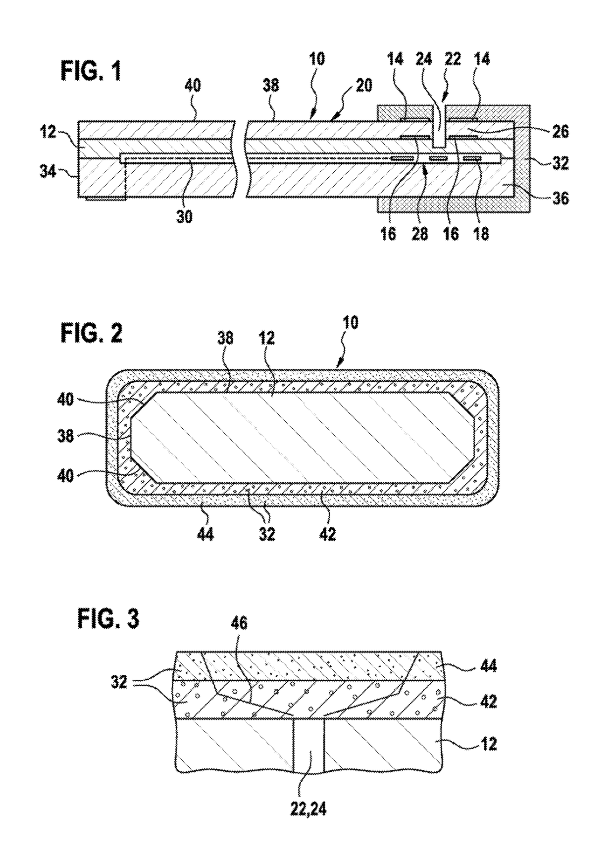
[0032]Sensor element 10 illustrated in FIG. 1 may be used for detecting physical and / or chemical properties of a measuring gas, whereby one or multiple properties may be detected. The present invention is described below in particular with regard to a qualitative and / or quantitative detection of a component of the gas, in particular with regard to a detection of an oxygen content in the measuring gas. The oxygen content may be detected in the form of a partial pressure and / or in the form of a percentage, for example. However, other types of gas components are also detectable in principle, for example nitrogen oxides, hydrocarbons, and / or hydrogen. Alternatively or additionally, however, other properties of the measuring gas are also detectable, such as the temperature, for example. The present invention is usable in particular in the field of automotive technology, so that the measuring gas chamber may in particular be an exhaust tract of an internal combustion engine, and the measu...


PUM

PropertyMeasurementUnit
temperatureaaaaaaaaaa

Abstract

A method for manufacturing a sensor element is provided for detecting at least one property of a measuring gas in a measuring gas chamber, in particular for detecting a proportion of a gas component in the measuring gas or a temperature of the measuring gas. The method includes the following steps: providing at least one solid electrolyte which includes at least one functional element; applying, at least in sections, at least one first layer made of a ceramic material to the solid electrolyte, the first layer having a first porosity after the application; and applying, at least in sections, at least one second layer made of a ceramic material, the second layer having a second porosity after the application, and the first layer differing from the second layer with respect to at least one material property. Moreover, a sensor element which is manufacturable according to this method is provided.

Description

BACKGROUND INFORMATION[0001]Numerous sensor elements and methods for detecting at least one property of a measuring gas in a measuring gas chamber are known from the related art. This may basically involve any physical and / or chemical properties of the measuring gas, and one or multiple properties may be detected. The present invention is described below in particular with regard to a qualitative and / or quantitative detection of a proportion of a gas component in the measuring gas, in particular with regard to a detection of an oxygen content in the measuring gas. The oxygen content may be detected in the form of a partial pressure and / or in the form of a percentage, for example. Alternatively or additionally, however, other properties of the measuring gas, such as the temperature, are also detectable.[0002]For example, sensor elements of this type may be designed as so-called lambda sensors, as are known, for example, from Konrad Reif (Ed.): Sensoren im Kraftfahrzeug [Automotive Se...

Claims


Application Information

Patent Timeline
Patent Type & Authority Patents(United States)
IPC IPC(8): G01N27/407G01N27/406
CPCG01N27/4074G01N27/4077G01N27/4071G01N27/4067
Inventor PETERS, CHRISTOPHMOSER, THOMASKUEHNLEIN, TOBIASDIEHL, LOTHARGUENSCHEL, HARALD
Owner ROBERT BOSCH GMBH
Why Eureka
Try Eureka