Process of ultrasonic spray pyrolysis deposition of one or more electrochromic and/or electrolytic films on a substrate

a technology of electrolytic film and ultrasonic spray, which is applied in liquid/solution decomposition chemical coating, instruments, non-metal conductors, etc., can solve the problems of unoptimized quality of resulting films, and achieve perfect covering, high layer uniformity, and improved electrochromic performance

Active Publication Date: 2019-04-09
INISMA +1
View PDF5 Cites 0 Cited by
  • Summary
  • Abstract
  • Description
  • Claims
  • Application Information

AI Technical Summary

Benefits of technology

[0011]Improved homogeneous thin electrochromic or electrolytic layer has also been obtained on large-scale substrates with high layer uniformity, perfect covering and improved electrochromic performances such as coloration efficiency, coloration contrast, low light diffusivity (haze), good cycling reversibility, durability, switching kinetics.
[0012]Finally, a multilayer stacking construction comprising at least one electrochromic and at least one electrolytic layer on a substrate is generated according to the process of the invention with a surprisingly good cycling reversibility.
[0031]The surfactant incorporation in the aqueous or organic precursor solution aims at lowering the surface tension to generate smaller droplets at the ultrasonic spraying nozzle and improves their wettability when deposited onto the heated substrate. The surfactant in the precursor solution also influences the solution viscosity and may prevent coalescence or aggregation of particles when the film will be formed.
[0046]The deposition follows a “x,y” patterning above the surface of the substrate according to an arc pattern with S-shaped move (1-6 mm spacing, preferably 4 mm spacing; by spacing it is intended the distance between two nozzle runs) at a constant speed of 5-50 mm / s, preferably 40 mm / s, with a constant z distance between nozzle and substrate of 3-6 cm, preferably 5.5 cm. The “x,y” deposition may be repeated 2-16 times keeping exactly the same pattern every odd passages (meaning passages #1, 3, 5 etc.) and shifting “x” or “y” coordinates by half of the spacing value every even passages (meaning passages #2, 4, 6 etc.), this in order to promote the formation of homogeneous and smooth deposited layers rather than furrowed ones.
[0050]One advantage of such bi- or triple layers construction, particularly after that a conductive top layer was deposited above it, is the straightforward elaboration at atmospheric pressure of a fully-functional “all solid” multilayer stacking construction, presenting excellent visual aspect with high homogeneity and few or no visual morphological defects. The multilayer stacking construction also shows excellent electrochemical, electrochromic and optical characteristics in terms of coloration contrast, coloration efficiency, low light scattering (quantified by haze), reversibility, durability, and switching kinetics.
[0057]By durability it is intended the evolution of reversibility value with electrochemical cycling (cyclic voltammetry). The more reversibility is stable and close to 100% over a large number of cycles, the more the device is considered as durable.

Problems solved by technology

Nevertheless the quality of the resulting films is not optimal, particularly in terms of homogeneity and electrochromic performances such as coloration contrast, coloration efficiency, reversibility, durability, switching kinetics, surface / interface defects.

Method used


Image

  • Process of ultrasonic spray pyrolysis deposition of one or more electrochromic and/or electrolytic films on a substrate
  • Process of ultrasonic spray pyrolysis deposition of one or more electrochromic and/or electrolytic films on a substrate
  • Process of ultrasonic spray pyrolysis deposition of one or more electrochromic and/or electrolytic films on a substrate

Examples


Embodiment Construction

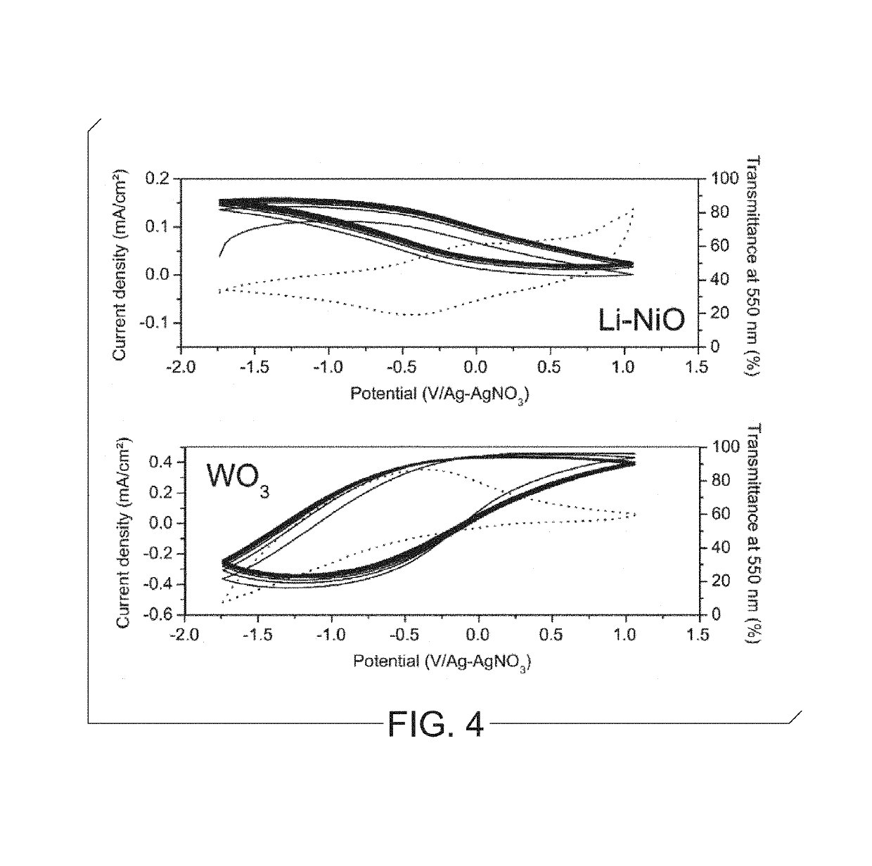
[0069]The process according to the invention is now illustrated in the following examples using Glass / TCO as substrate, wherein TCO is fluorine-doped tin oxide (FTO).

[0070]Different mono- or / and multilayered systems were obtained according to the following scheme:[0071]An Ultrasonic Spray Pyrolysis (USP) deposition of individual electrochromic stoichiometric or non-stoichiometric lithiated nickel oxide layer Liy—NiOx (further denoted as “Li—NiO”), electrochromic stoichiometric or non-stoichiometric tungsten oxide layer WO(3-y) (further denoted as “WO3”) and electrolytic lithium aluminosilicate (further denoted as “LAS”) layer (see step I of FIG. 9);[0072]An USP deposition of electrochromic+electrolytic bilayers, following different combinations: Li—NiO / LAS or WO3 / LAS (see step II of FIG. 9);[0073]An USP deposition of electrochromic+electrolytic+electrochromic trilayers, following different deposition orders: Li—NiO / LAS / WO3 or WO3 / LAS / Li—NiO (see step III of FIG. 9).

[0074]FIG. 9: pro...


PUM

PropertyMeasurementUnit
frequencyaaaaaaaaaa
frequencyaaaaaaaaaa
flow rateaaaaaaaaaa

Abstract

A process of making an electrochromic or an electrolytic film by Ultrasonic Spray Pyrolysis (USP) deposition on a substrate comprising:mixing a surfactant to an aqueous precursor solution comprising an electrochromic component or an electrolytic component to provide a spray solution;introducing the spray solution into an ultrasonic spray deposition nozzle at a constant flow rate between 0.1 mL / min and 2 mL / min and applying an ultrasonic frequency between 80 and 120 kHz to generate atomized droplets of the precursor solution;entraining the atomized droplets with a controlled jet of air as gas carrier at a pressure between 0.50 to 2.0 psi, onto a pre-heated substrate at a temperature of 200 to 450° C.;thermally converting the atomized droplets when depositing onto the pre-heated substrate to generate an electrochromic or an electrolytic film.

Description

BACKGROUND OF THE INVENTION[0001]The present invention relates to a process of making an electrochromic or an electrolytic film by Ultrasonic Spray Pyrolysis (USP) deposition on a substrate, at atmospheric pressure. The present invention also relates to a multilayer stacking construction of the electrochromic and electrolytic films on the substrate.DESCRIPTION OF RELATED ART[0002]Ultrasonic Spray Pyrolysis is well-known in the art and has recently been applied by R. C. Tenent, particularly in US 2011 / 0260124 to the deposition of electrochromic metal oxide films.[0003]Nevertheless the quality of the resulting films is not optimal, particularly in terms of homogeneity and electrochromic performances such as coloration contrast, coloration efficiency, reversibility, durability, switching kinetics, surface / interface defects. Moreover the process conditions are also to be improved to be efficient on a large-scale substrate at a moderate cost. Multilayers construction also needs to be imp...

Claims


Application Information

Patent Timeline
Patent Type & Authority Patents(United States)
IPC IPC(8): B05D3/00C03C17/34G02F1/1347G02F1/153G02F1/155G02F1/1523C23C18/12H01B1/08G02F1/15C23C18/02G02F1/1503
CPCG02F1/1523C23C18/1216C23C18/1225C23C18/1258C23C18/1291G02F1/1347G02F1/15G02F1/155G02F1/1525G02F1/1533H01B1/08C03C17/3417Y02P20/129C23C18/02G02F2202/38G02F1/1503
Inventor CLOOTS, RUDIHENRIST, CATHERINEDENAYER, JESSICAMAHO, ANTHONYCAMBIER, FRANCISLARDOT, VERONIQUEBISTER, GEOFFROYAUBRY, PHILIPPE
Owner INISMA
Why Eureka
Try Eureka