Circuit arrangement and method for gate-controlled power semiconductor devices
a gate-controlled, semiconductor technology, applied in the direction of pulse technique, electronic switching, transistors, etc., can solve the problems of short circuit between, damage to drive units and other system components, and the inability to control functionally capable switching elements through gate electrodes, etc., to avoid damage or at least reduce the effect of damage caused, low control power and high blocking voltag
- Summary
- Abstract
- Description
- Claims
- Application Information
AI Technical Summary
Benefits of technology
Problems solved by technology
Method used
Image
Examples
first embodiment
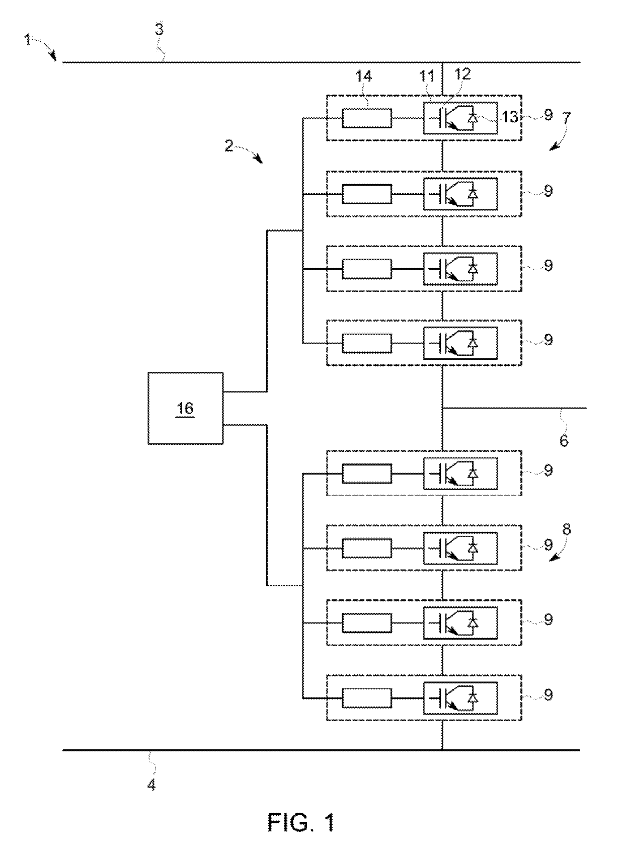
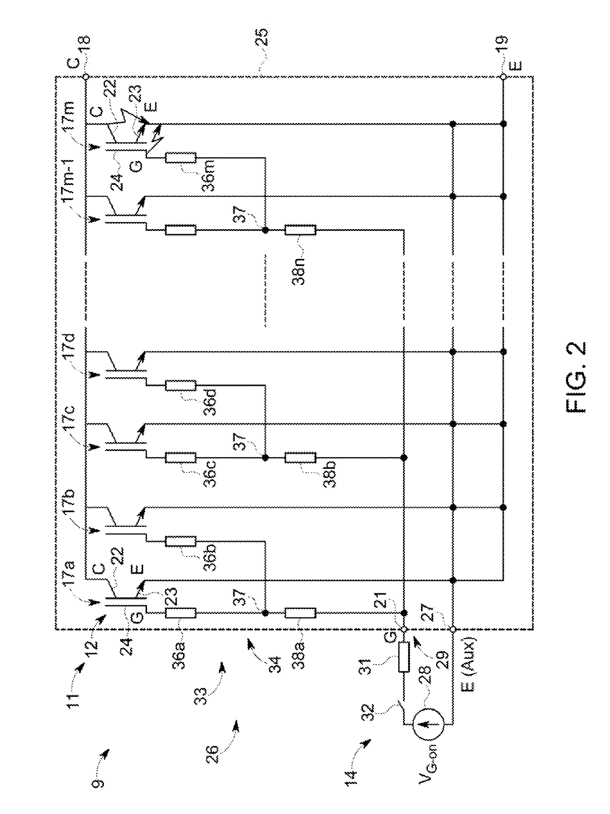
[0052]FIG. 2 shows a block image of a power electronic module 9, which includes a switch module 11 and a drive unit 14. As illustrated, the switch module 11 includes a plurality of switching elements 17a, 17b, 17c, 17d 17m−1, 17m, which are connected in parallel between a first connection 18, a second connection 19, and a control connection 21. The switch module 11 can include any suitable number of switching elements, but typically a minimum of two switching elements are arranged in parallel with each other.
[0053]In an embodiment, the switching element 17 may be a power semiconductor device, e.g., an IGBT, MOSFET, JFET or similar controllable power semiconductor switch, which can be switched between a conducting state and a non-conducting (or blocking) state through suitable control. In the Figs., for simplification of the following description, IGBTs are illustrated as the switching elements 17 and the associated free-wheeling diodes are omitted. In the following description the ...
second embodiment
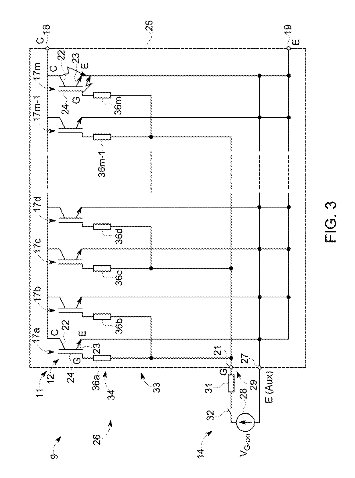
[0074]FIG. 3 shows a power electronic module 9, which includes a switch module 11 according to a The switch module 11 is similar to the switch module shown in FIG. 2 but the second resistances 38 have been omitted so that the first resistances 36 are connected through the connection points 37 directly to the gate connection 21.
[0075]Through suitable design of the resistance matrix 34 it can be ensured that, for a given drive voltage VG-on, which is applied by the drive unit 14 through a drive resistance 31 to the connections 19, 21 of the switch module 11, the gate-emitter voltage at the gate electrodes 24 of functionally capable, non-faulty switching elements 17 is greater than the threshold voltage VGE-th.
[0076]As an example, for the switch module 11 shown in FIG. 3, under the assumption that the electrical resistances of the first resistances 36 between the gate connection 21 and the gate electrodes 24 are substantially equal, i.e., so Rint=R11=R12= . . . =R1m, the following con...
third embodiment
[0080]FIG. 4 shows a switch module 11 according to a The switch module 11 is similar to the switch module shown in FIG. 2 but a fuse 39a, 39b, . . . , 39n is provided in each gate current path between the gate electrode 24 of each switching element 17 and the respective connecting point 37 for the group of switching elements. As shown in FIG. 4, each fuse 39 is connected between a first resistance 36 and the connecting point 17 for the group of switching elements. The fuses 39 can be safety fuses or resettable fuses, and depending on the resistance matrix 34, are designed or selected in such a way that they trigger in the event of a fault in order to separate the short-circuited gate electrode 24 of a faulty switching element 17 from the gate connection 21, whereas the other fuses associated with the non-faulty switching elements 17 are not affected.
[0081]In cases of a short-circuited gate structure of a faulty switching element, the resultant gate current, which is fed with the ap...
PUM
 Abstract
Description
Claims
Application Information
 - R&D
- Intellectual Property
- Life Sciences
- Materials
- Tech Scout
- Unparalleled Data Quality
- Higher Quality Content
- 60% Fewer Hallucinations
Browse by: Latest US Patents, China's latest patents, Technical Efficacy Thesaurus, Application Domain, Technology Topic, Popular Technical Reports.
© 2025 PatSnap. All rights reserved.Legal|Privacy policy|Modern Slavery Act Transparency Statement|Sitemap|About US| Contact US: help@patsnap.com


