

Photoelectric conversion layer composition and photoelectric conversion element
a photoelectric conversion and composition technology, applied in the direction of electrolytic capacitors, sustainable manufacturing/processing, final product manufacturing, etc., can solve the problems of inefficiency in conversion of weak light, high power generation cost, and common problems of conventional solar cells, so as to simplify the production process and improve the photoelectric conversion characteristic. , the effect of excellent photoelectric conversion characteristi
- Summary
- Abstract
- Description
- Claims
- Application Information
AI Technical Summary
Benefits of technology
Problems solved by technology
Method used
Image

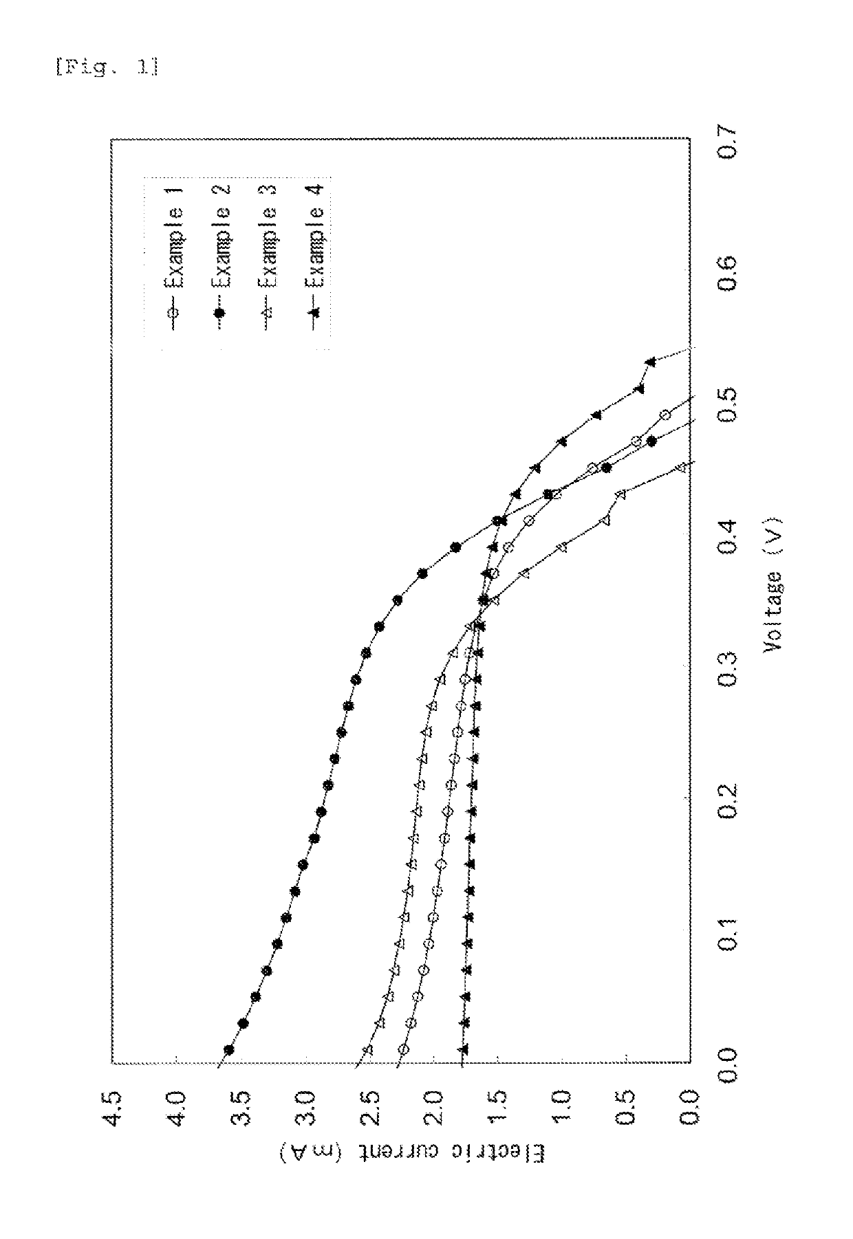
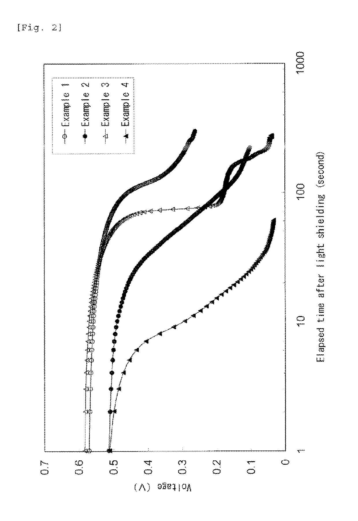
Examples
example 1
[0133]A titanium oxide dispersion was prepared by mixing 10 parts by weight of a titanium oxide particle (“ST-01” manufactured by Ishihara Sangyo Kaisha, Ltd., average primary particle diameter: 7 nm, specific surface area: 300 m2 / g, anatase-form crystal), 25 parts by weight of an anionic-polymer-containing dispersion (“Nafion 117” manufactured by Aldrich, 20% dispersion containing water and 1-propanol, ion exchange capacity: 0.95 to 1.03 meq / g, pH (25° C.)=1, area for one molecule to occupy: about 0.024 nm2) (that is, 5 parts by weight of an anionic polymer), 0.1 parts by weight of a dye (N719, manufactured by Tokyo Chemical Industry Co., Ltd., molecular weight: 1188.57, area for one molecule to occupy: about 1 nm2), and 65 parts by weight of methanol.
[0134]The resulting titanium oxide particle dispersion was applied on an ITO layer of an ITO-attached glass substrate (manufactured by Luminescence Technology Corp., size: 25 mm×25 mm, thickness of ITO layer: 0.14 μm) by squeegeeing a...
example 2
[0137]A slurry containing an ITO powder (manufactured by Aldrich, particle diameter: 2 / g) (a 10% by weight water dispersion containing 1 part by weight of the ITO powder and 0.1 parts by weight of a methyl cellulose (manufactured by Tokyo Chemical Industry Co., Ltd.)) was applied on an ITO layer of an ITO-attached glass substrate to give a porous layer (thickness: 5 μm). The resulting substrate was covered with platinum (thickness: 3.5 nm) by sputtering to give an electrode. The resulting electrode was composed of the ITO-attached glass substrate and the porous layer. A dye-sensitized solar cell was produced and evaluated in the same manner as in Example 1 except that the resulting electrode was used as the counter electrode having a porous layer.
example 3
[0138]A slurry containing a platinum on carbon powder (“IFPC40-II” manufactured by Ishifuku Metal Industry Co., Ltd.) (a 10% by weight water dispersion containing 1 part by weight of the platinum on carbon powder and 0.1 parts by weight of a methyl cellulose (manufactured by Tokyo Chemical Industry Co., Ltd.)) was applied on an ITO layer of an ITO-attached glass substrate to give a porous layer (thickness: 5 μm). The resulting electrode was composed of the ITO-attached glass substrate and the porous layer. A dye-sensitized solar cell was produced and evaluated in the same manner as in Example 1 except that the resulting electrode was used as the counter electrode having a porous layer.
PUM
| Property | Measurement | Unit |
|---|---|---|
| thickness | aaaaa | aaaaa |
| temperature | aaaaa | aaaaa |
| particle diameter | aaaaa | aaaaa |
Abstract
Description
Claims
Application Information